- 您现在的位置:买卖IC网 > PDF目录373702 > TS34118CS (Taiwan Semiconductor Co., Ltd.) Voice Switched Speakerphone Circuit PDF资料下载
参数资料
| 型号: | TS34118CS |
| 厂商: | Taiwan Semiconductor Co., Ltd. |
| 英文描述: | Voice Switched Speakerphone Circuit |
| 中文描述: | 语音开关扬声器电路 |
| 文件页数: | 11/20页 |
| 文件大小: | 328K |
| 代理商: | TS34118CS |
TS34118
11-20
2004/09 rev. B
Attenuator Control Block
4) The circuit will switch to the slow idle mode when a) both talkers are quiet (no speech present), or b) when one talker’s
speech level is continuously overridden by noise at the other speaker’s location.
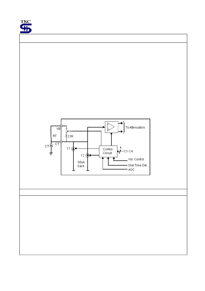
The time required to switch the circuit between transmit, receive, fast idle and slow idle is determined in part by the
components at the CT pin (pin 14). (see the section on Switch Time for a more complete explanation of the switching
time components). A schematic of the CT circuitry is shown in Figure 6, and operates as follows:
-RT is typically 120K
, and CT is typically 5.0μF.
-To switch to the receive mode, I1 is turned on (I2 is off), charging the external capacitor to +240mV above VB. (An
internal clamp prevents further charging of the capacitor.)
-To switch to the transmit mode, I2 is turned on (I1 is off) bringing down the voltage on the capacitor to –240mV with
respect to VB.
-To switch to idle quickly (fast idle), the current sources are turned off, and the internal 2.0K
resistor is switched in,
discharging the capacitor to VB with a time constant = 2.0K×CT.
-To switch to idle slowly (slowly idle), the current sources are turned off, the switch at the internal 2.0K
resistor is
open, and the capacitor discharges to VB through the external resistor RT with a time constant = RT × CT.
Figure 6. CT Attenuator Control Block Circuit
Microphone Amplifier
The microphone amplifier (pins 10,11) has the non-inverting input internally connected to V
B
, while the inverting input and
the output are pinned out. Unlike most op-amps, the amplifier has an all-NPN output stage, which maximizes phase
margin and gain-bandwidth. This feature ensures stability at gains less than unity, as well as with a wide range of reactive
loads. The open loop gain is typically 80dB (f<100Hz), and the gain-bandwidth is typically 1.0MHz (see Figure 16). The
maximum p-p output swing is typically 1.0 volt less than Vcc with an output impedance of <10
until current limited is
reached (typically 1.5mA).Input bias current at MCI is typically 40nA out of the pin.
The muting function (Pin 12), when activated, will reduce the gain of the amplifier to
≈
-39dB (with RMI=5.0K
) by shorting
output to the inverting input (see Figure 7). The mute input has a threshold of
≈
1.5 volts, and the voltage at this pin must
be kept within the range of ground and Vcc (see Figure 17). If the mute function is not used, the pin should be grounded.
相关PDF资料 |
PDF描述 |
|---|---|
| TS34119 | Low Power Audio Amplifier |
| TS34119CD | Low Power Audio Amplifier |
| TS34119CS | Low Power Audio Amplifier |
| TS34119CA | COAXIAL T CNNCTRS NON-BH BNC AUTO T-CNNCTR F-M-F |
| TS3431AILT | 1.24V programmable shunt voltage reference |
相关代理商/技术参数 |
参数描述 |
|---|---|
| TS34118CS28 | 功能描述:电信语音调制 IC Voice Switch Speaker phone Circuit RoHS:否 制造商:Epson Electronics America 产品: 应用:Voice Guidance product 封装 / 箱体:PQFP-52 电源电压-最大:3.6 V, 5.5 V 最大工作温度: 最小工作温度: 封装: |
| TS34118CS28 C8 | 制造商:SKMI/Taiwan 功能描述:Voice Switched Speakerphone Circuit 28-Pin SOP Tube |
| TS34118CS28C8 | 制造商:TSC 制造商全称:Taiwan Semiconductor Company, Ltd 功能描述:Voice Switched Speakerphone Circuit |
| TS34119 | 制造商:TSC 制造商全称:Taiwan Semiconductor Company, Ltd 功能描述:Low Power Audio Amplifier |
| TS34119_07 | 制造商:TSC 制造商全称:Taiwan Semiconductor Company, Ltd 功能描述:Low Power Audio Amplifier |
发布紧急采购,3分钟左右您将得到回复。