- 您现在的位置:买卖IC网 > PDF目录373702 > TS34118CS (Taiwan Semiconductor Co., Ltd.) Voice Switched Speakerphone Circuit PDF资料下载
参数资料
| 型号: | TS34118CS |
| 厂商: | Taiwan Semiconductor Co., Ltd. |
| 英文描述: | Voice Switched Speakerphone Circuit |
| 中文描述: | 语音开关扬声器电路 |
| 文件页数: | 17/20页 |
| 文件大小: | 328K |
| 代理商: | TS34118CS |
TS34118
17-20
2004/09 rev. B
Design Equations
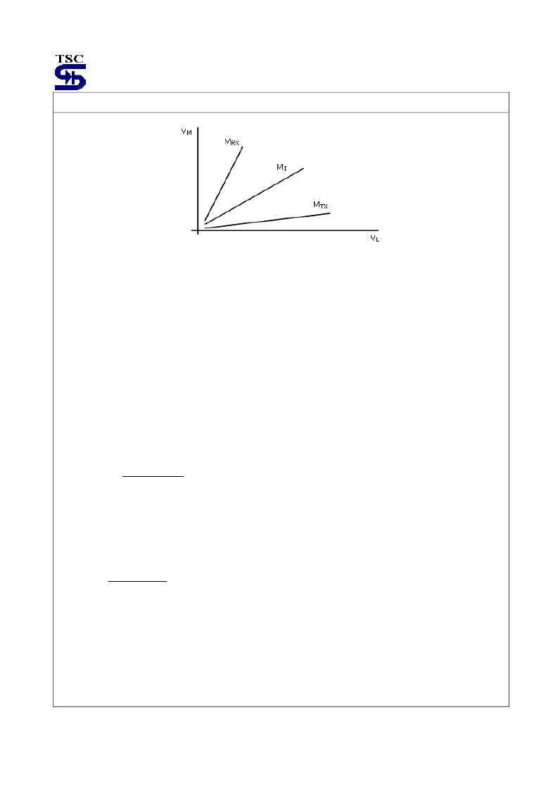
Figure 11. Switching Threshold
The “M” terms are the slopes of the lines (0.52,0.024, and 0.0019) which are the coefficients of the three equations.
The M
RX
line represents the receive to transmit threshold in that it defines the microphone signal level necessary to
switch to transmit in the presence of a given receive signal level. The M
TX
line represents the transmit to receive
threshold, The M
I
line represents the idle condition, and defines the threshold level on one side (transmit or receive)
necessary to overcome noise on the other.
Some comments on the above graph:
-Acoustic coupling and side tone coupling were not included in Equations 7 and 12. Those couplings will affect the
actual performance of the final speakerphone due to their interaction with speech at the microphone, and the
receive signal coming in at Tip/Ring. The effects of those couplings are difficult to predict due to their associated
phase shifts and frequency response. In some cases the coupling signal will add, and other times subtract from the
incoming signal. The physical design of the speakerphone enclosure, as well as the specific phone line to which it
is connected , will affect the acoustic and side tone couplings, respectively.
-The M
RX
line helps define the maximum acoustic coupling allowed in a system, which can be found from the
following equation:
G
AC-MAX
=
MA
G
R3
2
R1
×
×
(Equation 13)
Equation 13 is independent of the volume control setting. Conversely, the acoustic coupling of a designed system helps
determine the minimum slope of that line. Using the component values in Equation 13 yields a G
AC-MAX
of –37dB.
Experience has shown, however, that an acoustic coupling loss of >40dB is desirable.
-The M
TX
line helps define the maximum side tone coupling (G
ST
) allowed in the system, which can be found from
the following equation:
G
ST
=
FO
G
R2
2
R4
×
×
(Equation 14)
Using the component values in Equation 14 yields a maximum side tone of 0dB. Experience has shown, however, that
a minimum of 6.0dB loss is preferable.
The above equations can be used to determine the resistor values for the level detector inputs. Equation 6 can be used
to determine the R1/R3 ratio, and Equation 10 can be used to determine the R4/R2 ratio. In Figure 10, R1-R4 each
represent the combined impedance of the resistor and coupling capacitor at each level detector input. The magnitude of
each RC’s impedance should be kept within the range of 2.0K-15K
in the voice band (due to the typical signal levels
present) to obtain the best performance from the level detectors. The specific R and C at each location will determine
the frequency response of that level detector.
相关PDF资料 |
PDF描述 |
|---|---|
| TS34119 | Low Power Audio Amplifier |
| TS34119CD | Low Power Audio Amplifier |
| TS34119CS | Low Power Audio Amplifier |
| TS34119CA | COAXIAL T CNNCTRS NON-BH BNC AUTO T-CNNCTR F-M-F |
| TS3431AILT | 1.24V programmable shunt voltage reference |
相关代理商/技术参数 |
参数描述 |
|---|---|
| TS34118CS28 | 功能描述:电信语音调制 IC Voice Switch Speaker phone Circuit RoHS:否 制造商:Epson Electronics America 产品: 应用:Voice Guidance product 封装 / 箱体:PQFP-52 电源电压-最大:3.6 V, 5.5 V 最大工作温度: 最小工作温度: 封装: |
| TS34118CS28 C8 | 制造商:SKMI/Taiwan 功能描述:Voice Switched Speakerphone Circuit 28-Pin SOP Tube |
| TS34118CS28C8 | 制造商:TSC 制造商全称:Taiwan Semiconductor Company, Ltd 功能描述:Voice Switched Speakerphone Circuit |
| TS34119 | 制造商:TSC 制造商全称:Taiwan Semiconductor Company, Ltd 功能描述:Low Power Audio Amplifier |
| TS34119_07 | 制造商:TSC 制造商全称:Taiwan Semiconductor Company, Ltd 功能描述:Low Power Audio Amplifier |
发布紧急采购,3分钟左右您将得到回复。