- 您现在的位置:买卖IC网 > PDF目录373745 > TSS463C (Atmel Corp.) VAN Data Link Controller with Serial Interface PDF资料下载
参数资料
| 型号: | TSS463C |
| 厂商: | Atmel Corp. |
| 英文描述: | VAN Data Link Controller with Serial Interface |
| 中文描述: | 凡数据与串行接口链路控制器 |
| 文件页数: | 39/59页 |
| 文件大小: | 492K |
| 代理商: | TSS463C |
第1页第2页第3页第4页第5页第6页第7页第8页第9页第10页第11页第12页第13页第14页第15页第16页第17页第18页第19页第20页第21页第22页第23页第24页第25页第26页第27页第28页第29页第30页第31页第32页第33页第34页第35页第36页第37页第38页当前第39页第40页第41页第42页第43页第44页第45页第46页第47页第48页第49页第50页第51页第52页第53页第54页第55页第56页第57页第58页第59页
39
TSS463C
7601B–AUTO–02/06
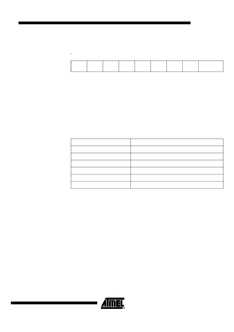
Message Length And Status
Register
The message length and status register at address (base_address + 0x03) is also 8 bits
wide. It indicates the length of reserved for the message in the Message DATA RAM
area.
Read/Write register.
M_L [4:0]: Message Length
The 5 high bits of this register allows the user to specify either the length of the message
to be transmitted, or the maximum length of a message receivable in the pointed recep-
tion buffer.
Note:
The first byte in this register does not contain data, but the length of the message
received. This implies that the length value has to be equal to or greater than the maxi-
mum length of a message to be received in this buffer (or the length of a message to be
transmitted) plus 1, thus allowing a maximum length of 30 bytes and a minimum length
of 0 byte.
If the value of this field is “illegal” (i.e 0x00) then this message pointer is defined as
being a link (see Message pointer and register and “Linked Channels” on page 52).
CHER: Channel Error Status
and Abort Command
As status, this bit is set by the TSS463C when error occurs in transmission or on a
received frame. The user must reset it.
To abort the transmission defined in the channel, this bit can be set to 1 by the user (see
Section “Activate, Idle and Sleep Modes”, page 51 and “Abort” on page 49)
CHTx: Channel Transmitted and
Transmit Enable Command
CHRx: Channel Received and
Receive Enable Command
The 2 low order bits of this register contain the message status. Together with the RNW
and RTR bits of the command register (base_address + 0x01), they define the message
type of this channel (see section “Message Types” on page 44). As a general rule, the
status bits are only set by the TSS463C, so the user must reset them to perform a trans-
mission (CHTx) or/and a reception (CHRx). The received and transmitted bits are only
set if the corresponding frame is without errors or if the retry count has been exceeded.
7
6
5
4
3
2
1
0
M_L 4
M_L 3
M_L 2
M_L 1
M_L 0
CHER
CHTx
CHRx
base_address
+ 0x03
M_L [4:0] = 0x00
Linked channel
M_L [4:0] = 0x01
Frame with no DATA field
(1)
M_L [4:0] = 0x02
Frame with 1 DATA byte
- - - - - - -
- - - - - - - - - - - - - - - - - - - - - -
M_L [4:0] = 0x1D
Frame with 28 DATA bytes
M_L [4:0] = 0x1E
Frame with 29 DATA bytes
M_L [4:0] = 0x1F
Frame with 30 DATA bytes
Note:
1.
Different of a reply request frame with no in-frame reply (deferred reply).
相关PDF资料 |
PDF描述 |
|---|---|
| TSS4B02G | Single Phase 4.0 Amps. Glass Passivated Super Fast Bridge Rectifiers |
| TSS4B03G | Single Phase 4.0 Amps. Glass Passivated Super Fast Bridge Rectifiers |
| TSS4B01G | Single Phase 4.0 Amps. Glass Passivated Super Fast Bridge Rectifiers |
| TSS5G45S | TOSHIBA SOLID STATE AC RELAY |
| TSS5J45S | TOSHIBA SOLID STATE AC RELAY |
相关代理商/技术参数 |
参数描述 |
|---|---|
| TSS463C-TERA-9 | 功能描述:网络控制器与处理器 IC ASICS RoHS:否 制造商:Micrel 产品:Controller Area Network (CAN) 收发器数量: 数据速率: 电源电流(最大值):595 mA 最大工作温度:+ 85 C 安装风格:SMD/SMT 封装 / 箱体:PBGA-400 封装:Tray |
| TSS463C-TERZ-9 | 制造商:Atmel Corporation 功能描述: |
| TSS463C-TESZ-9 | 功能描述:网络控制器与处理器 IC ASICS RoHS:否 制造商:Micrel 产品:Controller Area Network (CAN) 收发器数量: 数据速率: 电源电流(最大值):595 mA 最大工作温度:+ 85 C 安装风格:SMD/SMT 封装 / 箱体:PBGA-400 封装:Tray |
| TSS463D | 制造商:未知厂家 制造商全称:未知厂家 功能描述:Industrial Control IC |
| TSS463R | 制造商:未知厂家 制造商全称:未知厂家 功能描述:Industrial Control IC |
发布紧急采购,3分钟左右您将得到回复。