- 您现在的位置:买卖IC网 > PDF目录98305 > TVP5010PFP (TEXAS INSTRUMENTS INC) COLOR SIGNAL DECODER, PQFP80 PDF资料下载
参数资料
| 型号: | TVP5010PFP |
| 厂商: | TEXAS INSTRUMENTS INC |
| 元件分类: | 颜色信号转换 |
| 英文描述: | COLOR SIGNAL DECODER, PQFP80 |
| 封装: | POWERPAD, PLASTIC, TQFP-80 |
| 文件页数: | 11/59页 |
| 文件大小: | 250K |
| 代理商: | TVP5010PFP |
第1页第2页第3页第4页第5页第6页第7页第8页第9页第10页当前第11页第12页第13页第14页第15页第16页第17页第18页第19页第20页第21页第22页第23页第24页第25页第26页第27页第28页第29页第30页第31页第32页第33页第34页第35页第36页第37页第38页第39页第40页第41页第42页第43页第44页第45页第46页第47页第48页第49页第50页第51页第52页第53页第54页第55页第56页第57页第58页第59页
2–7
Input Signal
Output Signal
VO
VI
Coring Threshold
t
Figure 2–9. Transfer Curve of Coring Circuit
2.2.3
Chrominance Processing
A quadrature demodulator removes the U and V components from the composite signal in composite video
mode, or the U and V components from the chroma signal in S-video mode. The U/V signals then pass
through the gain control stage for chroma saturation adjustment. The U and V components pass through
a comb filter to eliminate cross-chrominance noise. Phase shifting the digitally-controlled oscillator controls
hue. The block includes an automatic color killer (ACK) circuit that suppresses the chroma processing when
the color burst of the video signal is weak or not present.
2.2.4
Clock Circuits
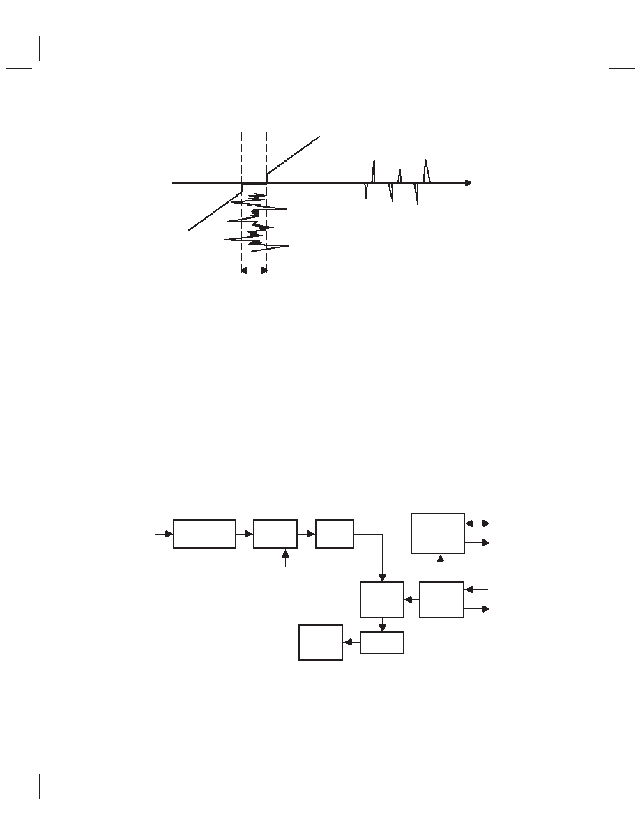
An Internal line-locked PLL generates the system and pixel clocks. Figure 2–10 shows a simplified clock
circuit diagram. The digital control oscillator generates the reference signal for the horizontal PLL.
The DCO outputs a signal that is fed to the D/A converter. The D/A converter outputs a line-locked clock
signal (LCLK). The DCO requires a 26.8 or a 24.576 MHz clock as an input. The input for the DCO may enter
terminal XTAL1 as TTL. Another input for the DCO may be a 26.8 or 24.576 MHz crystal connected across
terminals XTAL1 and XTAL2. The crystal input requires passive tuning circuits to activate the internal crystal
oscillator circuitry. Figure 2–11 shows the various reference clock configurations.
Lowpass Filter
Sync Detector
Phase
Detector
Loop
Filter
Line-Locked
Clock
PLL
Digital
Control
Oscillator
Crystal
Clock
Generator
DAC
Clock
Generator
Circuit
SCLK
PCLK
XTL1
XTL2
Digitized
Video
Figure 2–10. Clock Circuit Diagram
相关PDF资料 |
PDF描述 |
|---|---|
| TVP5020CPFP | COLOR SIGNAL DECODER, PQFP80 |
| TVP5020 | COLOR SIGNAL DECODER, PQFP80 |
| TVP5022 | COLOR SIGNAL DECODER, PQFP80 |
| TVP5031PFP | COLOR SIGNAL DECODER, PQFP80 |
| TVP5040CPFP | COLOR SIGNAL DECODER, PQFP80 |
相关代理商/技术参数 |
参数描述 |
|---|---|
| TVP5020 | 制造商:TI 制造商全称:Texas Instruments 功能描述:NTSC/PAL VIDEO DECODER |
| TVP5020CPFP | 制造商:Rochester Electronics LLC 功能描述:- Bulk |
| TVP5020PFC | 制造商:未知厂家 制造商全称:未知厂家 功能描述: |
| TVP5020TQFP | 制造商:TI 制造商全称:Texas Instruments 功能描述:NTSC/PAL VIDEO DECODER |
| TVP5021PFP | 功能描述:视频 IC NTSC/PAL DIGITAL VIDEO DECODER RoHS:否 制造商:Fairchild Semiconductor 工作电源电压:5 V 电源电流:80 mA 最大工作温度:+ 85 C 封装 / 箱体:TSSOP-28 封装:Reel |
发布紧急采购,3分钟左右您将得到回复。