- 您现在的位置:买卖IC网 > PDF目录98305 > TVP5010PFP (TEXAS INSTRUMENTS INC) COLOR SIGNAL DECODER, PQFP80 PDF资料下载
参数资料
| 型号: | TVP5010PFP |
| 厂商: | TEXAS INSTRUMENTS INC |
| 元件分类: | 颜色信号转换 |
| 英文描述: | COLOR SIGNAL DECODER, PQFP80 |
| 封装: | POWERPAD, PLASTIC, TQFP-80 |
| 文件页数: | 13/59页 |
| 文件大小: | 250K |
| 代理商: | TVP5010PFP |
第1页第2页第3页第4页第5页第6页第7页第8页第9页第10页第11页第12页当前第13页第14页第15页第16页第17页第18页第19页第20页第21页第22页第23页第24页第25页第26页第27页第28页第29页第30页第31页第32页第33页第34页第35页第36页第37页第38页第39页第40页第41页第42页第43页第44页第45页第46页第47页第48页第49页第50页第51页第52页第53页第54页第55页第56页第57页第58页第59页
2–8
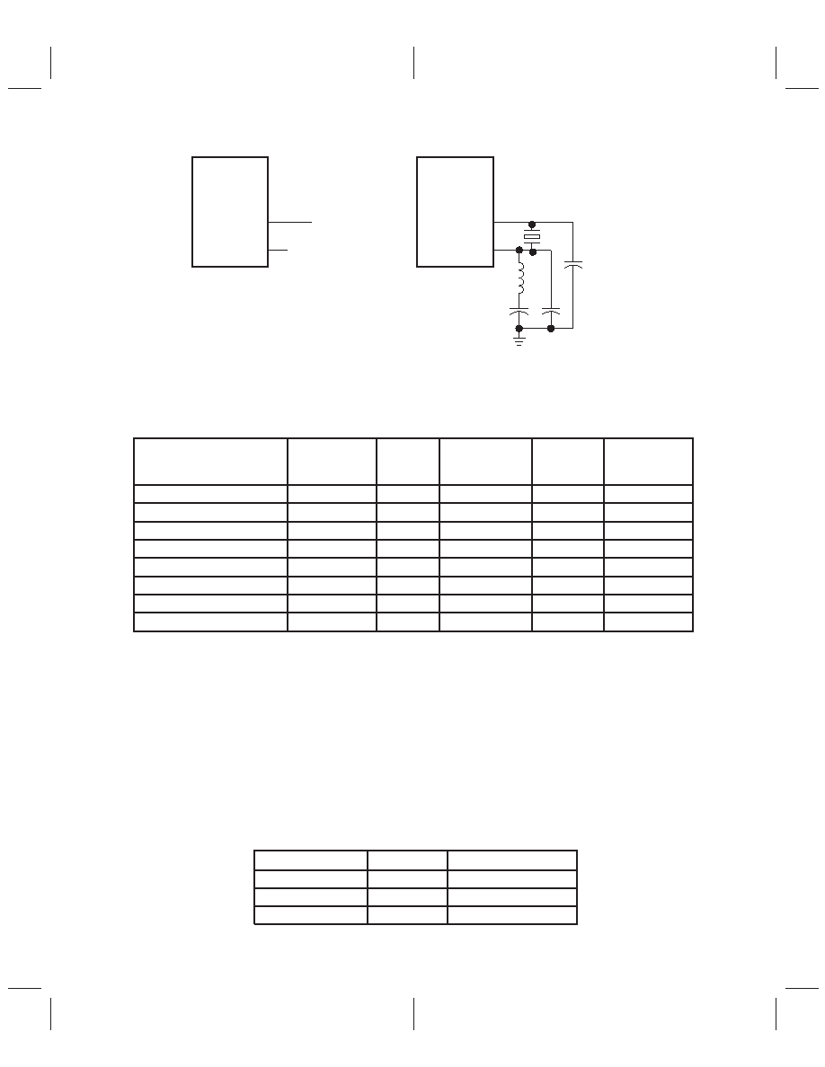
TVP5000
XTAL1
XTAL2
35
36
TVP5000
XTAL1
XTAL2
35
36
26.8 MHz or
24.576 MHz
Crystal
26.8 MHz or
24.576 MHz
TTL Clock
Figure 2–11. Reference Clock Configurations
The sampling frequencies that control the number of pixels per line differ depending on the video format and
standards. Table 2–1 shows a summary of the sampling frequencies.
Table 2–1. Summary of the Line Frequencies, Data Rates, and Pixel Counts
STANDARDS
HORIZONTAL
LINE RATE
(kHz)
PIXELS
PER LINE
ACTIVE PIXELS
PER LINE
PIXEL
PCLK RATE
(MHz)
SYSTEM clk2
FREQUENCY
(MHz)
NTSC, square-pixel
15.73426
780
640
12.2727
24.54
NTSC, ITU-R BT.601
15.73426
858
720
13.5
27.0
PAL (B,D,G,H,I), square-pixel
15.625
944
768
14.75
29.5
PAL (B,D,G,H,I), ITU-R BT.601
15.625
864
720
13.5
27.0
PAL(M), square-pixel
15.73426
780
640
12.2727
24.54
PAL(M), ITU-R BT.601
15.73426
858
720
13.5
27.0
PAL(N), square-pixel
15.625
944
768
14.75
29.5
PAL(N), ITU-R BT.601
15.625
864
720
13.5
27.0
2.3
I2C Interface
The I2C standard consists of two signals, serial input/output data (SDA) line and input/output clock line
(SCL), that carry information between the devices connected to the bus. A third signal (I2CA) is used for
slave address selection. Although the I2C system can be multimastered, the TVP5010 will function as a
slave device only.
Both SDA and SCL are bidirectional lines that connect to a positive supply voltage via a pullup resistor. When
the bus is free, both lines are high.
The slave address (I2CA) should be tied high or low to distinguish between two TVP5010 devices commonly
on the I2C bus.
Table 2–3 summarizes the terminal functions of the I2C mode host interface.
Table 2–2. I2C Host Port Terminal Description
SIGNAL
TYPE
DESCRIPTION
I2CA
I
Slave address selection
SCL
I/O (OD)
Input/output clock line
SDA
I/O (OD)
Input/output data line
相关PDF资料 |
PDF描述 |
|---|---|
| TVP5020CPFP | COLOR SIGNAL DECODER, PQFP80 |
| TVP5020 | COLOR SIGNAL DECODER, PQFP80 |
| TVP5022 | COLOR SIGNAL DECODER, PQFP80 |
| TVP5031PFP | COLOR SIGNAL DECODER, PQFP80 |
| TVP5040CPFP | COLOR SIGNAL DECODER, PQFP80 |
相关代理商/技术参数 |
参数描述 |
|---|---|
| TVP5020 | 制造商:TI 制造商全称:Texas Instruments 功能描述:NTSC/PAL VIDEO DECODER |
| TVP5020CPFP | 制造商:Rochester Electronics LLC 功能描述:- Bulk |
| TVP5020PFC | 制造商:未知厂家 制造商全称:未知厂家 功能描述: |
| TVP5020TQFP | 制造商:TI 制造商全称:Texas Instruments 功能描述:NTSC/PAL VIDEO DECODER |
| TVP5021PFP | 功能描述:视频 IC NTSC/PAL DIGITAL VIDEO DECODER RoHS:否 制造商:Fairchild Semiconductor 工作电源电压:5 V 电源电流:80 mA 最大工作温度:+ 85 C 封装 / 箱体:TSSOP-28 封装:Reel |
发布紧急采购,3分钟左右您将得到回复。