- 您现在的位置:买卖IC网 > PDF目录98306 > TVP5150PBSR (TEXAS INSTRUMENTS INC) COLOR SIGNAL DECODER, PQFP32 PDF资料下载
参数资料
| 型号: | TVP5150PBSR |
| 厂商: | TEXAS INSTRUMENTS INC |
| 元件分类: | 颜色信号转换 |
| 英文描述: | COLOR SIGNAL DECODER, PQFP32 |
| 封装: | GREEN, PLASTIC, TQFP-32 |
| 文件页数: | 18/68页 |
| 文件大小: | 917K |
| 代理商: | TVP5150PBSR |
第1页第2页第3页第4页第5页第6页第7页第8页第9页第10页第11页第12页第13页第14页第15页第16页第17页当前第18页第19页第20页第21页第22页第23页第24页第25页第26页第27页第28页第29页第30页第31页第32页第33页第34页第35页第36页第37页第38页第39页第40页第41页第42页第43页第44页第45页第46页第47页第48页第49页第50页第51页第52页第53页第54页第55页第56页第57页第58页第59页第60页第61页第62页第63页第64页第65页第66页第67页第68页
Functional Description
19
May 2006
SLES043A
3.18 I2C Host Interface
The I2C standard consists of two signals, serial input/output data line (SDA) and input/output clock line (SCL),
which carry information between the devices connected to the bus. A third signal (I2CSEL) is used for slave
address selection. Although the I2C system can be multimastered, the TVP5150 device functions as a slave
device only.
Both SDA and SCL must be connected to a positive supply voltage via a pullup resistor. When the bus is free,
both lines are high. The slave address select terminal (I2CSEL) enables the use of two TVP5150 devices tied
to the same I2C bus. At power up, the status of the I2CSEL is polled. Depending on the write and read
addresses to be used for the TVP5150 device, it can either pulled low or high through a resistor. This terminal
is multiplexed with YOUT7 and hence must not be tied directly to ground or VDD. Table 36 summarizes the
terminal functions of the I2C-mode host interface.
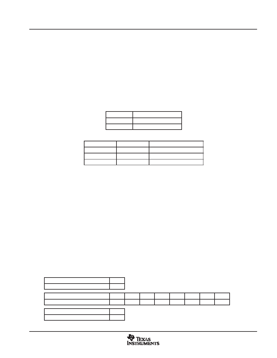
Table 35. Write Address Selection
I2CSEL
WRITE ADDRESS
0
B8h
1
BAh
Table 36. I2C Terminal Description
SIGNAL
TYPE
DESCRIPTION
I2CSEL (YOUT7)
I
Slave address selection
SCL
I/O (open drain)
Input/output clock line
SDA
I/O (open drain)
Input/output data line
Data transfer rate on the bus is up to 400 kbits/s. The number of interfaces connected to the bus is dependent
on the bus capacitance limit of 400 pF. The data on the SDA line must be stable during the high period of the
SCL except for start and stop conditions. The high or low state of the data line can only change with the clock
signal on the SCL line being low. A high-to-low transition on the SDA line while the SCL is high indicates an
I2C start condition. A low-to-high transition on the SDA line while the SCL is high indicates an I2C stop
condition.
Every byte placed on the SDA must be 8 bits long. The number of bytes which can be transferred is
unrestricted. Each byte must be followed by an acknowledge bit. The acknowledge-related clock pulse is
generated by the I2C master.
3.18.1
I2C Write Operation
Data transfers occur utilizing the following illustrated formats.
An I2C master initiates a write operation to the TVP5150 device by generating a start condition (S) followed
by the TVP5150 I2C address (as shown below), in MSB first bit order, followed by a 0 to indicate a write cycle.
After receiving an acknowledge from the TVP5150 device, the master presents the subaddress of the register,
or the first of a block of registers it wants to write, followed by one or more bytes of data, MSB first. The
TVP5150 device acknowledges each byte after completion of each transfer. The I2C master terminates the
write operation by generating a stop condition (P).
Step 1
0
I2C Start (master)
S
Step 2
7
6
5
4
3
2
1
0
I2C General address (master)
1
0
1
0
X
0
Step 3
9
I2C Acknowledge (slave)
A
相关PDF资料 |
PDF描述 |
|---|---|
| TVP5151IPBSQ1 | COLOR SIGNAL DECODER, PQFP32 |
| TVP5151IPBSRQ1 | COLOR SIGNAL DECODER, PQFP32 |
| TVP5151IPBSR | COLOR SIGNAL DECODER, PQFP32 |
| TVP5151IPBS | COLOR SIGNAL DECODER, PQFP32 |
| TVP5151IZQCR | COLOR SIGNAL DECODER, PBGA48 |
相关代理商/技术参数 |
参数描述 |
|---|---|
| TVP5150PBSRG4 | 制造商:Texas Instruments 功能描述: |
| TVP5151 | 制造商:TI 制造商全称:Texas Instruments 功能描述:Ultralow-Power NTSC/PAL/SECAM Video Decoder |
| TVP5151EVM | 功能描述:视频 IC 开发工具 TVP5151 Eval Mod RoHS:否 制造商:Texas Instruments 产品:Evaluation Boards 类型:YPbPr to RGBHV Converters 工具用于评估:LMH1251 工作电源电压:5 V |
| TVP5151IPBS | 功能描述:视频 IC UltraLo-Pwr NTSC/ RoHS:否 制造商:Fairchild Semiconductor 工作电源电压:5 V 电源电流:80 mA 最大工作温度:+ 85 C 封装 / 箱体:TSSOP-28 封装:Reel |
| TVP5151IPBSR | 功能描述:视频 IC UltraLo-Pwr NTSC/PAL SECAM Vid Dec RoHS:否 制造商:Fairchild Semiconductor 工作电源电压:5 V 电源电流:80 mA 最大工作温度:+ 85 C 封装 / 箱体:TSSOP-28 封装:Reel |
发布紧急采购,3分钟左右您将得到回复。