- 您现在的位置:买卖IC网 > PDF目录18804 > TXM-869-ES_ (Linx Technologies Inc)XMITTER RF 869MHZ 10PIN SMD PDF资料下载
参数资料
| 型号: | TXM-869-ES_ |
| 厂商: | Linx Technologies Inc |
| 文件页数: | 8/11页 |
| 文件大小: | 0K |
| 描述: | XMITTER RF 869MHZ 10PIN SMD |
| 产品变化通告: | ES Series Frequency Change 22/Dec/2010 |
| 标准包装: | 40 |
| 系列: | ES |
| 频率: | 869MHz |
| 应用: | 住宅/楼宇自动化,工业控制和监控 |
| 调制或协议: | AM,OOK |
| 数据传输率 - 最大: | 56 kbps |
| 功率 - 输出: | 4dBm |
| 电流 - 传输: | 8.5mA |
| 数据接口: | PCB,表面贴装 |
| 天线连接器: | PCB,表面贴装 |
| 电源电压: | 2.1 V ~ 4 V |
| 工作温度: | 0°C ~ 70°C |
| 封装/外壳: | 模块 |
| 包装: | 散装 |
| 其它名称: | TXM-869-ES TXM-869-ES_-ND |
�� �
�
�task. A professionally designed�
�for� practical� or� ergonomic� reasons,� thus,�
�an� alternative� antenna� style� such� as� a�
�helical,� loop,� or� patch� may� be� utilized�
�4.� In� many� antenna� designs,� particularly� 1/4-wave�
�whips,� the� ground� plane� acts� as� a� counterpoise,�
�forming,� in� essence,� a� 1/2-wave� dipole.� For� this�
�DIPOLE�
�reason,� adequate� ground� plane� area� is� essential.�
�surface� area� >� the� overall� length� of� the� 1/4-wave�
�radiating� element.� This� is� often� not� practical� due� to�
�instances,� a� designer� must� make� the� best� use� of� the�
�0.1� μ� F�
�it� is� often� advantageous� to� share� a� single�
�antenna.� To� accomplish� this,� an� antenna�
�switch� must� be� used� to� provide� isolation�
�between� the� modules� so� that� the� full�
�sensitive� front� end� of� the� receiver.� There�
�are� a� wide� variety� of� antenna� switches� that�
�are� cost-effective� and� easy� to� use.� Among�
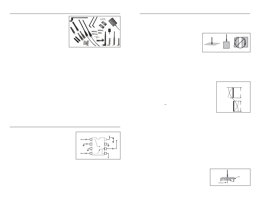
�ANTENNA CONSIDERATIONS�
�The� choice� of� antennas� is� a� critical�
�and� often� overlooked� design�
�consideration.� The� range,�
�performance,� and� legality� of� an� RF� link�
�are� critically� dependent� upon� the�
�antenna.� While� adequate� antenna�
�performance� can� often� be� obtained� by�
�trial� and� error� methods,� antenna�
�design� and� matching� is� a� complex�
�Figure� 16:� Linx� Antennas�
�antenna,� such� as� those� from� Linx,� will�
�help� ensure� maximum� performance� and� FCC� compliance.�
�Linx� transmitter� modules� typically� have� an� output� power� that� is� slightly� higher�
�than� the� legal� limits.� This� allows� the� designer� to� use� an� inefficient� antenna,� such�
�as� a� loop� trace� or� helical,� to� meet� size,� cost,� or� cosmetic� requirements� and� still�
�achieve� full� legal� output� power� for� maximum� range.� If� an� efficient� antenna� is�
�used,� then� some� attenuation� of� the� output� power� will� likely� be� needed.� This� can�
�easily� be� accomplished� by� using� the� LADJ� line� or� a� T-pad� attenuator.� For� more�
�details� on� T-pad� attenuator� design,� please� see� Application� Note� AN-00150.�
�A� receiver� antenna� should� be� optimized� for� the� frequency� or� band� in� which� the�
�receiver� operates� and� to� minimize� the� reception� of� off-frequency� signals.� The�
�efficiency� of� the� receiver’s� antenna� is� critical� to� maximizing� range� performance.�
�Unlike� the� transmitter� antenna,� where� legal� operation� may� mandate� attenuation�
�or� a� reduction� in� antenna� efficiency,� the� receiver’s� antenna� should� be� optimized�
�as� much� as� is� practical.�
�It� is� usually� best� to� utilize� a� basic� quarter-wave� whip� until� your� prototype� product�
�is� operating� satisfactorily.� Other� antennas� can� then� be� evaluated� based� on� the�
�cost,� size,� and� cosmetic� requirements� of� the� product.� You� may� wish� to� review�
�Application� Note� AN-00500� “Antennas:� Design,� Application,� Performance”�
�ANTENNA� SHARING�
�In� cases� where� a� transmitter� and� receiver�
�module� are� combined� to� form� a� transceiver,� VDD�
�Transmitter�
�Module� 0.1� μ� F�
�Antenna�
�0.1� μ� F�
�GND�
�0.1� μ� F�
�GND�
�Receiver�
�transmitter� output� power� is� not� put� on� the� Module�
�0.1� μ� F�
�Select�
�Figure� 17:� Typical� Antenna� Switch�
�the� most� popular� are� switches� from� Macom� and� NEC.� Look� for� an� antenna�
�switch� that� has� high� isolation� and� low� loss� at� the� desired� frequency� of� operation.�
�Generally,� the� Tx� or� Rx� status� of� a� switch� will� be� controlled� by� a� product’s�
�GENERAL� ANTENNA� RULES�
�The� following� general� rules� should� help� in� maximizing� antenna� performance.�
�1.� Proximity� to� objects� such� as� a� user’s� hand,� body,� or� metal� objects� will� cause� an�
�antenna� to� detune.� For� this� reason,� the� antenna� shaft� and� tip� should� be�
�positioned� as� far� away� from� such� objects� as� possible.�
�2.� Optimum� performance� will� be� obtained�
�from� a� 1/4-� or� 1/2-wave� straight� whip�
�mounted� at� a� right� angle� to� the� ground�
�plane.� In� many� cases,� this� isn’t� desirable�
�OPTIMUM�
�NOT� RECOMMENDED�
�U� S� ABLE�
�Figure� 18:� Ground� Plane� Orientation�
�and� the� corresponding� sacrifice� in� performance� accepted.�
�3.� If� an� internal� antenna� is� to� be� used,� keep� it� away� from� other� metal� components,�
�particularly� large� items� like� transformers,� batteries,� PCB� tracks,� and� ground�
�planes.� In� many� cases,� the� space� around� the� antenna� is� as� important� as� the�
�antenna� itself.� Objects� in� close� proximity� to� the� antenna� can� cause� direct�
�detuning,� while� those� farther� away� will� alter� the� antenna’s� symmetry.�
�VERTICAL� λ� /4� GROUNDED�
�ANTENNA� (MARCONI)�
�E�
�ELEMENT�
�λ� /4�
�The� ground� plane� can� be� a� metal� case� or� ground-fill� I�
�areas� on� a� circuit� board.� Ideally,� it� should� have� a�
�GROUND�
�PLANE�
�VIRTUAL� λ� /4� λ� /4�
�DIPOLE�
�size� and� configuration� constraints.� In� these�
�Figure� 19:� Dipole� Antenna�
�area� available� to� create� as� much� ground� plane� as�
�possible� in� proximity� to� the� base� of� the� antenna.� In� cases� where� the� antenna� is�
�remotely� located� or� the� antenna� is� not� in� close� proximity� to� a� circuit� board,�
�ground� plane,� or� grounded� metal� case,� a� metal� plate� may� be� used� to� maximize�
�the� antenna’s� performance.�
�5.� Remove� the� antenna� as� far� as� possible� from� potential� interference� sources.� Any�
�frequency� of� sufficient� amplitude� to� enter� the� receiver’s� front� end� will� reduce�
�system� range� and� can� even� prevent� reception� entirely.� Switching� power�
�supplies,� oscillators,� or� even� relays� can� also� be� significant� sources� of� potential�
�interference.� The� single� best� weapon� against� such� problems� is� attention� to�
�placement� and� layout.� Filter� the� module’s� power� supply� with� a� high-frequency�
�bypass� capacitor.� Place� adequate� ground� plane� under� potential� sources� of� noise�
�to� shunt� noise� to� ground� and� prevent� it� from� coupling� to� the� RF� stage.� Shield�
�noisy� board� areas� whenever� practical.�
�6.� In� some� applications,� it� is� advantageous� to�
�place� the� module� and� antenna� away� from� the�
�microprocessor,� but� the� user� may� also� make� the� selection� manually.� In� some�
�main� equipment.� This� can� avoid� interference�
�CA� S� E�
�cases,� where� the� characteristics� of� the� Tx� and� Rx� antennas� need� to� be� different�
�or� antenna� switch� losses� are� unacceptable,� it� may� be� more� appropriate� to� utilize�
�problems� and� allows� the� antenna� to� be�
�oriented� for� optimum� performance.� Always� use�
�NUT�
�GROUND� PLANE�
�(MAY� BE� NEEDED)�
�two� discrete� antennas.�
�Page� 14�
�50� Ω� coax,� like� RG-174,� for� the� remote� feed.�
�Figure 20: Remote Ground Plane�
�Page� 15�
�相关PDF资料 |
PDF描述 |
|---|---|
| 14A-10R-20 | XFRMR PWR 115/230V 10V 1.0A |
| TXE-315-KH2 | TRANSMITTER RF 315MHZ SMT |
| 14A-10R-28 | XFRMR PWR 115/230V 14V .72A |
| MAX2903ETI+ | IC TX 868MHZ 200MW 28TQFN |
| 9922-18RED | LEAD PLUG STK BAN 2MM RED 18" |
相关代理商/技术参数 |
参数描述 |
|---|---|
| TXM-869-ES_ | 功能描述:XMITTER RF 869MHZ 10PIN SMD RoHS:是 类别:RF/IF 和 RFID >> RF 发射器 系列:ES 标准包装:4,000 系列:- 频率:310MHz ~ 440MHz 应用:- 调制或协议:UHF,ASK 数据传输率 - 最大:20 kBaud 功率 - 输出:1dBm ~ 5dBm 电流 - 传输:10mA 数据接口:PCB,表面贴装 天线连接器:PCB,表面贴装 存储容量:- 特点:- 电源电压:2.2 V ~ 4 V 工作温度:-40°C ~ 85°C 封装/外壳:16-LSSOP(0.154",3.90mm 宽) 包装:带卷 (TR) |
| TXM-900-HP3-PPO | 功能描述:射频模块 RF Transmitter 900MHz 8-CH SIP Pack RoHS:否 制造商:Linx Technologies 产品:Transceiver Modules 频带:902 MHz to 928 MHz 输出功率:- 15.5 dBm to + 12.5 dBm 接口类型:UART 工作电源电压:- 0.3 VDC to + 5.5 VDC 传输供电电流:38.1 mA 接收供电电流:22.7 mA 天线连接器类型:U.FL 最大工作温度:+ 85 C 尺寸:1.15 mm x 0.63 mm x 0.131 mm |
| TXM-900-HP3-PPO_ | 功能描述:TRANSMITTER RF 900MHZ 8-CHANNEL RoHS:是 类别:RF/IF 和 RFID >> RF 发射器 系列:HP3 标准包装:4,000 系列:- 频率:310MHz ~ 440MHz 应用:- 调制或协议:UHF,ASK 数据传输率 - 最大:20 kBaud 功率 - 输出:1dBm ~ 5dBm 电流 - 传输:10mA 数据接口:PCB,表面贴装 天线连接器:PCB,表面贴装 存储容量:- 特点:- 电源电压:2.2 V ~ 4 V 工作温度:-40°C ~ 85°C 封装/外壳:16-LSSOP(0.154",3.90mm 宽) 包装:带卷 (TR) |
| TXM-900-HP3-PPS | 功能描述:射频模块 RF Transmitter900MHz 8&100-CH SIP Pack RoHS:否 制造商:Linx Technologies 产品:Transceiver Modules 频带:902 MHz to 928 MHz 输出功率:- 15.5 dBm to + 12.5 dBm 接口类型:UART 工作电源电压:- 0.3 VDC to + 5.5 VDC 传输供电电流:38.1 mA 接收供电电流:22.7 mA 天线连接器类型:U.FL 最大工作温度:+ 85 C 尺寸:1.15 mm x 0.63 mm x 0.131 mm |
| TXM-900-HP3-PPS_ | 制造商:Linx Technologies Inc 功能描述:TRANSMTR RF 900MHZ 8PAR/120SRLCH |
发布紧急采购,3分钟左右您将得到回复。