- 您现在的位置:买卖IC网 > PDF目录69541 > TXS80ZD-NP2R2H (POWER-ONE INC) 1-OUTPUT 200 W DC-DC REG PWR SUPPLY MODULE PDF资料下载
参数资料
| 型号: | TXS80ZD-NP2R2H |
| 厂商: | POWER-ONE INC |
| 元件分类: | 电源模块 |
| 英文描述: | 1-OUTPUT 200 W DC-DC REG PWR SUPPLY MODULE |
| 封装: | 2.400 X 3.450 INCH, 0.500 INCH HEIGHT, 3/4 BRICK PACKAGE-14 |
| 文件页数: | 7/27页 |
| 文件大小: | 2635K |
| 代理商: | TXS80ZD-NP2R2H |
第1页第2页第3页第4页第5页第6页当前第7页第8页第9页第10页第11页第12页第13页第14页第15页第16页第17页第18页第19页第20页第21页第22页第23页第24页第25页第26页第27页
Product Specification
TXS Series: 75…120 A DC-DC Converters
36 to 75 V DC Input, 1.2, 1.5, 1.8, 2.0 and 2.5 V Output, 90 W to 250 W
REV. FEB 18, 2003
15 of 27
www.power-one.com
with the negative return Vo (-). More layout
information can be found on the TXS CD ROM.
The following points should be observed, when
sense wires are used:
The output voltage of the TXS modules should
not be increased above +20 % of Uo nom. This
limit includes any increase due to remote
sense and an output voltage set-point
adjustment over the trim function.
The output power of the TXS module is
defined as the output voltages at the power
pins multiplied by the load current. When the
output voltage is increased to compensate
voltage drops, the output power from the
converter is increased as well. The power
should not exceed its maximum rating.
If not used, the remote sense pins have to be
connected as short as possible to Vo (+) and
Vo (-) respectively. If not connected, the
output voltage shows an increased line and
load regulation.
The sense wires are loaded with a small signal
current. Do not place resistors or filters into
the sense wires.
The PCB layout of the power tracks to the load
should result in a low wiring inductance.
Otherwise the dynamic performance even with
sense wires is degraded.
Do not use filter capacitors between sense
and power pins. They could possibly influence
the stability of the module.
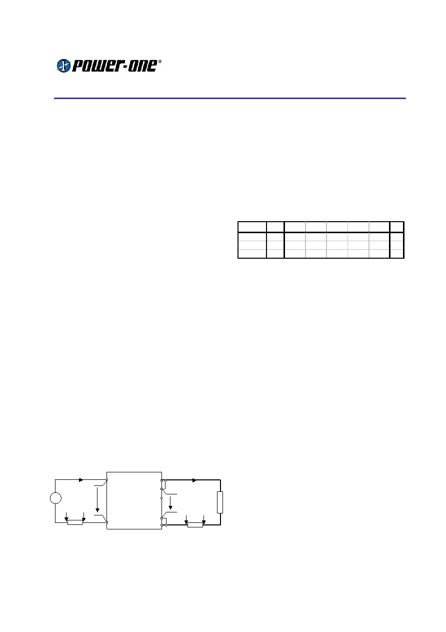
Power loss and Efficiency
The measurement of loss and efficiency at very
high output current converters is quite difficult. To
avoid measurement errors, a Kelvin connection
directly at the module terminals should be used.
sense should be wired directly to the power pins.
Vo (+)
Sense (+)
Trim
Sense (-)
Vo (-)
R Load
Uo
Vi (+)
Vi (-)
ON/OFF
6
4
7
8
5
2
3
1
Io
USH = RSHo * Io
Ui
USH = RSHi * Ii
Ii
+
Figure 36:
Efficiency Measurement Set Up
Open sense wires result in measurement errors. A
low drop precision shunt, rated for 100A should be
used to measure the output current.
To remember: At 100 A, a 1 m
resistor in trace
or over a bad contact in the measurement set up
can produce as much as 100 mV of voltage drop
or a measuring error of 100 mV 100 A = 10 W !
The loss and efficiency measurements in the
graphs were done in a test system at room
temperature.
To
calculate
the
approximate
dissipation at elevated base plate temperatures,
the correction factors of the following table can be
used:
I o / TBP
110
100
90
80
70
60
46
100A
1.18
1.12
1.08
1.05
1.03
1.02
1
80A
1.11
1.09
1.07
1.05
1.03
1.01
1
60A
1.07
1.06
1.04
1.03
1.02
1.01
1
Table 7:
Correction
factor
k
for
different
output currents at elevated base
plate temperatures TBP.
Dissipation at TA: PLoss= Pi - Po = Po (1/η - 1)
Dissipation at TBP: PLoss(TBP) = PLoss(Graph) k
The
dissipation
at
elevated
base
plate
temperatures is needed to determine the cooling
requirements ( page 23: Thermal considerations).
Output Over Voltage Protection
The units have a built in over voltage protection,
which prevent an uncontrolled increase of the
output voltage in case of catastrophic failures of
the converter. The over voltage protection consist
of a second control loop, which is independent of
the main regulating circuit.
The protection is set to 125 % Uo set (Models ZY,
ZA, ZB, ZC) and 115 % Uo set (Model ZD).
The over voltage protection is not switching, but
regulating, so that the converter can’t be
accidentally turned of by noise or EMI. Output
voltage adjustment over sense or trim can’t trigger
the over voltage protection, because the protection
level is tracking with Uo set.
Operation in Parallel
Paralleling of two converters is not possible.
Operation in Series
TXS units can be connected in series. Consult the
factory for additional information if a serial
connection of modules is planned.
相关PDF资料 |
PDF描述 |
|---|---|
| W9725G6IB-18 | 16M X 16 DDR DRAM, 0.35 ns, PBGA84 |
| W9864G6EB-7 | 4M X 16 SYNCHRONOUS DRAM, 5.5 ns, PBGA60 |
| WE128K8200CQ | 128K X 8 EEPROM 5V MODULE, 200 ns, CDIP32 |
| WED9LC6816V1512BI | SPECIALTY MEMORY CIRCUIT, PBGA153 |
| WS128K32-35G2TMEA | 128K X 32 MULTI DEVICE SRAM MODULE, 35 ns, CQFP68 |
相关代理商/技术参数 |
参数描述 |
|---|---|
| TXS-86-515-S | 制造商:FLOYD BELL 功能描述:Alarm, Piezoelectric, 92 dBA to 103 dBA @ 2 Ft., Extra Loud Siren, 5-15VDC |
| TXS-86-515-SR | 制造商:FLOYD BELL 功能描述:Alarm, Piezoelectric, 92 dBA to 103 dBA @ 2 Ft., Extra Loud Siren, 5-15VDC |
| TX-SAW433S-Z-RFM | 制造商:AUREL 功能描述:RF MODULE TX OOK 434MHZ EXT ANT 制造商:AUREL 功能描述:RF MODULE, TX, OOK, 434MHZ, EXT ANT 制造商:AUREL 功能描述:RF MODULE, TX, OOK, 434MHZ, EXT ANT, Frequency:433.92MHz, Supply Voltage Min:4.5 |
| TX-SDK-V1/NOPB | 功能描述:数据转换 IC 开发工具 TX-SDK-V1 EVAL BRD RoHS:否 制造商:Texas Instruments 产品:Demonstration Kits 类型:ADC 工具用于评估:ADS130E08 接口类型:SPI 工作电源电压:- 6 V to + 6 V |
| TX-SDK-V2/NOPB | 功能描述:电源管理IC开发工具 Eval Brd fr Ultrasnd Transmit Solution RoHS:否 制造商:Maxim Integrated 产品:Evaluation Kits 类型:Battery Management 工具用于评估:MAX17710GB 输入电压: 输出电压:1.8 V |
发布紧急采购,3分钟左右您将得到回复。