- 您现在的位置:买卖IC网 > PDF目录68561 > WBLXT9785EHC.D0 (CORTINA SYSTEMS INC) DATACOM, INTERFACE CIRCUIT, PQFP208 PDF资料下载
参数资料
| 型号: | WBLXT9785EHC.D0 |
| 厂商: | CORTINA SYSTEMS INC |
| 元件分类: | 网络接口 |
| 英文描述: | DATACOM, INTERFACE CIRCUIT, PQFP208 |
| 封装: | ROHS COMPLIANT, PLASTIC, HQFP -208 |
| 文件页数: | 48/222页 |
| 文件大小: | 3158K |
| 代理商: | WBLXT9785EHC.D0 |
第1页第2页第3页第4页第5页第6页第7页第8页第9页第10页第11页第12页第13页第14页第15页第16页第17页第18页第19页第20页第21页第22页第23页第24页第25页第26页第27页第28页第29页第30页第31页第32页第33页第34页第35页第36页第37页第38页第39页第40页第41页第42页第43页第44页第45页第46页第47页当前第48页第49页第50页第51页第52页第53页第54页第55页第56页第57页第58页第59页第60页第61页第62页第63页第64页第65页第66页第67页第68页第69页第70页第71页第72页第73页第74页第75页第76页第77页第78页第79页第80页第81页第82页第83页第84页第85页第86页第87页第88页第89页第90页第91页第92页第93页第94页第95页第96页第97页第98页第99页第100页第101页第102页第103页第104页第105页第106页第107页第108页第109页第110页第111页第112页第113页第114页第115页第116页第117页第118页第119页第120页第121页第122页第123页第124页第125页第126页第127页第128页第129页第130页第131页第132页第133页第134页第135页第136页第137页第138页第139页第140页第141页第142页第143页第144页第145页第146页第147页第148页第149页第150页第151页第152页第153页第154页第155页第156页第157页第158页第159页第160页第161页第162页第163页第164页第165页第166页第167页第168页第169页第170页第171页第172页第173页第174页第175页第176页第177页第178页第179页第180页第181页第182页第183页第184页第185页第186页第187页第188页第189页第190页第191页第192页第193页第194页第195页第196页第197页第198页第199页第200页第201页第202页第203页第204页第205页第206页第207页第208页第209页第210页第211页第212页第213页第214页第215页第216页第217页第218页第219页第220页第221页第222页
Page 141
Cortina Systems LXT9785 and LXT9785E Advanced 8-Port 10/100 Mbps PHY Transceivers
LXT9785/LXT9785E
Datasheet
249241, Revision 11.0
16 April 2007
4.9 100 Mbps Operation
4.9
100 Mbps Operation
4.9.1
100BASE-X Network Operations
During 100BASE-X operation, the LXT9785/LXT9785E transmits and receives 5-bit
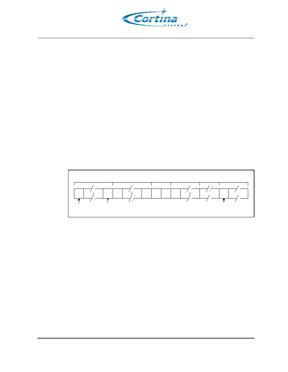
symbols across the network link. Figure 27 shows the structure of a standard frame
packet. When the MAC is not actively transmitting data, the LXT9785/LXT9785E sends
out Idle symbols on the line.
In 100BASE-TX mode, the device scrambles the data and transmits it to the network
using MLT-3 line code. The MLT-3 signals received from the network are de-scrambled
and decoded, and sent across the RMII to the MAC.
In 100BASE-FX mode, the LXT9785/LXT9785E transmits and receives NRZI signals
across the LVPECL interface. An external 100BASE-FX transceiver module is required to
complete the fiber connection.
As shown in Figure 27, the MAC starts each transmission with a preamble pattern. As
soon as the LXT9785/LXT9785E detects the start of preamble, it transmits a J/K Start-of-
Stream Delimiter (SSD) symbol to the network. It then encodes and transmits the rest of
the packet, including the balance of the preamble, the Start-of-Frame Delimiter (SFD),
packet data, and CRC. Once the packet ends, the LXT9785/LXT9785E transmits the T/R
End-of-Stream Delimiter (ESD) symbol and then returns to transmitting Idle symbols.
4.9.2
100BASE-X Protocol Sublayer Operations
In a 7-layer communications model, the LXT9785/LXT9785E is a Physical Layer 1 (PHY)
device. The LXT9785/LXT9785E implements the Physical Coding Sublayer (PCS),
Physical Medium Attachment (PMA), and Physical Medium Dependent (PMD) sublayers
of the reference model defined by the IEEE 802.3u specification. The following
paragraphs discuss the LXT9785/LXT9785E operation from the reference model point of
view.
4.9.2.1
PCS Sublayer
The Physical Coding Sublayer (PCS) provides the RMII interface, as well as the 4B/5B
encoding/decoding function. For 100BASE-TX and 100BASE-FX operation, the PCS
layer provides IDLE symbols to the PMD-layer line driver as long as TxEN is de-asserted.
For 10T operation, the PCS layer merely provides a bus interface and serialization/de-
serialization function. 10T operation does not use the 4B/5B encoder.
Figure 27
100BASE-X Frame Format
P0
P1
P6
SFD
64-Bit Preamble
(8 Octets)
Start-of-Frame
Delimiter (SFD)
DA
SA
Destination and Source
Address (6 Octets each)
L1
L2
Packet Length
(2 Octets)
D0
D1
Dn
Data Field
(Pad to minimum packet size)
Frame Check Field
(4 Octets)
CRC
I0
InterFrame Gap / Idle Code
(> 12 Octets)
Replaced by
/T/R/ code-groups
End-of-Stream Delimiter (ESD)
IFG
Replaced by
/J/K/ code-groups
Start-of-Stream
Delimiter (SSD)
相关PDF资料 |
PDF描述 |
|---|---|
| WBLXT9785HC.C2V | DATACOM, INTERFACE CIRCUIT, PQFP208 |
| WBLXT9785HC.D0-865112 | DATACOM, INTERFACE CIRCUIT, PQFP208 |
| WBLXT9785HC.D0-865113 | DATACOM, INTERFACE CIRCUIT, PQFP208 |
| WBLXT9785HC.D0 | DATACOM, INTERFACE CIRCUIT, PQFP208 |
| WBLXT9785HE.C2V | DATACOM, INTERFACE CIRCUIT, PQFP208 |
相关代理商/技术参数 |
参数描述 |
|---|---|
| WBLXT9785HC.D0 | 功能描述:IC TXRX 8PORT ETHERNET 208-HQFP RoHS:是 类别:集成电路 (IC) >> 接口 - 驱动器,接收器,收发器 系列:- 标准包装:1,000 系列:- 类型:收发器 驱动器/接收器数:2/2 规程:RS232 电源电压:3 V ~ 5.5 V 安装类型:表面贴装 封装/外壳:16-SOIC(0.295",7.50mm 宽) 供应商设备封装:16-SOIC 包装:带卷 (TR) |
| WBLXT9785HC.D0-865112 | 功能描述:TXRX ETH OCT LP COMM 208-HQFP RoHS:是 类别:集成电路 (IC) >> 接口 - 驱动器,接收器,收发器 系列:- 产品培训模块:Lead (SnPb) Finish for COTS Obsolescence Mitigation Program 标准包装:50 系列:- 类型:收发器 驱动器/接收器数:1/1 规程:RS422,RS485 电源电压:4.75 V ~ 5.25 V 安装类型:通孔 封装/外壳:8-DIP(0.300",7.62mm) 供应商设备封装:8-PDIP 包装:管件 产品目录页面:1402 (CN2011-ZH PDF) |
| WBLXT9785HC.D0-865113 | 制造商:Cortina Systems Inc 功能描述:PHY 8-CH 10Mbps/100Mbps 208-Pin PQFP |
| WBLXT9785HE.D0-865114 | 制造商:Cortina Systems Inc 功能描述:PHY 8-CH 10Mbps/100Mbps 208-Pin PQFP |
| WBM-DATA | 制造商:Thomas & Betts 功能描述: |
发布紧急采购,3分钟左右您将得到回复。