- 您现在的位置:买卖IC网 > PDF目录11832 > XR82C684CJTR/44-F (Exar Corporation)IC UART CMOS QUAD 44PLCC PDF资料下载
参数资料
| 型号: | XR82C684CJTR/44-F |
| 厂商: | Exar Corporation |
| 文件页数: | 65/107页 |
| 文件大小: | 0K |
| 描述: | IC UART CMOS QUAD 44PLCC |
| 标准包装: | 500 |
| 特点: | * |
| 通道数: | 4,QUART |
| FIFO's: | 3 字节 |
| 电源电压: | 5V |
| 安装类型: | 表面贴装 |
| 封装/外壳: | 44-LCC(J 形引线) |
| 供应商设备封装: | 44-PLCC(16.59x16.59) |
| 包装: | 带卷 (TR) |
第1页第2页第3页第4页第5页第6页第7页第8页第9页第10页第11页第12页第13页第14页第15页第16页第17页第18页第19页第20页第21页第22页第23页第24页第25页第26页第27页第28页第29页第30页第31页第32页第33页第34页第35页第36页第37页第38页第39页第40页第41页第42页第43页第44页第45页第46页第47页第48页第49页第50页第51页第52页第53页第54页第55页第56页第57页第58页第59页第60页第61页第62页第63页第64页当前第65页第66页第67页第68页第69页第70页第71页第72页第73页第74页第75页第76页第77页第78页第79页第80页第81页第82页第83页第84页第85页第86页第87页第88页第89页第90页第91页第92页第93页第94页第95页第96页第97页第98页第99页第100页第101页第102页第103页第104页第105页第106页第107页
XR82C684
.
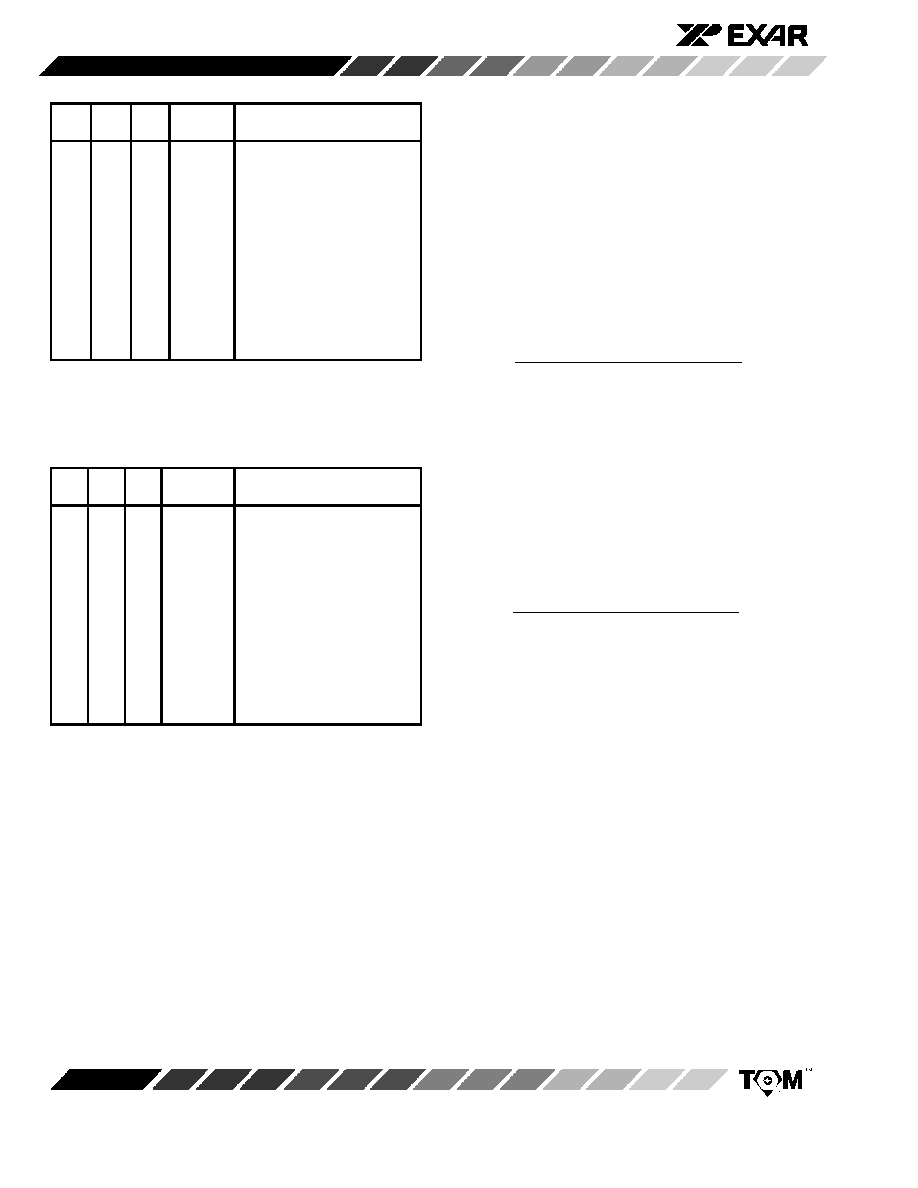
Bit
6
Bit
5
Bit
4
C/T
Mode
Timing Source
5"
$ $+
8 8
'6 *
%(
8) 8
'6 *
) %(
8-<= $ !(( & .
(
5"
$ $+
(
5"
$ $+# !((
& .
(
8-<= $
(
8-<= $ !(( & .
Note: The “shaded” options are only available in the 68 pin
PLCC.
Table 13. ACR1[6:4] Bit Field Definition - C/T#1
Bit
6
Bit
5
Bit
4
C/T
Mode
Timing Source
5"
$ $+
8 8
'6 *
%(
8! 8
'6 *
! %(
8-<= $ !(( & .
(
5"
$ $+
(
5"
$ $+#
!(( & .
(
8-<= $
(
8-<= $ !(( & .
Note: The “shaded” options are only available in the 68 pin
PLCC.
Table 13A. ACR2[6:4] Bit Field Definition - C/T#2
" ( Sections D.3.1 D.3.2 ,('
& *%
-( - ; 3# (% "
(%
-( D D I
& E (#
(%('( % 3(
3 3 -%
D.3.1 Timer Mode:
Please note that of the two C/T Modes, the Timer Mode is
the only mode which is relevant to the function of Bit Rate
Selection.
However, for completeness, the Counter
Mode is also discussed below.
$ ( # - '% % ,
(( ,% %I 3 3 % ( (%
3('
( '
'6 ( % * ' % *
-( ,(%%# � < - '
% % ,
( , (
' .8 '
'6 * & ( ( &
)2 %I3# (,((, * -D (%
+ (# +4 E%# %I3#
(,((, * -D (% + (# +
$* - (% ,
( ( #
*I'& * %
(, - %I 3 '
"%% % *
3%7
- I'& L
Frequency of Selected Timing Source
T PCTURQT 0 + PCTLRQ
37 P�Q L ' % * � ,(% (
'(
*
P<Q L ' % * < ,(% (
'(
*
(' - (% % .8 '
'6 %(,
&
� '('(&# %
(, ( (% -.
*I'& * - %(,
* # (
# ( * - ' "%% % *
3%7
Frequency of Selected Timing Source
4 T PCTURQT0 + PCTLRQ
' % * � < ,(%% &
', & (# 3(
& ,( 6 **'
"
* '&'
* %I 3 - ,(%
( %(,
% ( �-< '( *
%%(,, / �:51 '
Table 1
- % ' ( %
& %%I /
�:51 ' '%% - (
' ((, '&'
,( 3 ((, '&'
%(,
'
% % ( � <
�:5 5!H %% (# ( $ %
,(%% $P4Q $P4Q# (% % ' ' '&'
*
%I 3 (%
3% % * - %
( (' ( , # (* ' (( (%
, , ( ( (
%6 ,(%% $ $ $P4Q -
$P4Q ' '
& (%%(, (
%%(,, /+ �:51 '
Table 1
$ $5 # 3# '
% '
& % -
相关PDF资料 |
PDF描述 |
|---|---|
| ST16C454CJ68-F | IC UART QUAD 68PLCC |
| ST16C454IJ68-F | IC UART QUAD 68PLCC |
| VE-25D-IY | CONVERTER MOD DC/DC 85V 50W |
| ST16C654CQ64TR-F | IC UART FIFO 64B QUAD 64LQFP |
| XR16V564IV80-F | IC UART FIFO 32B QUAD 80LQFP |
相关代理商/技术参数 |
参数描述 |
|---|---|
| XR82C684CJTR-F | 功能描述:UART 接口集成电路 Quad Channel UART RoHS:否 制造商:Texas Instruments 通道数量:2 数据速率:3 Mbps 电源电压-最大:3.6 V 电源电压-最小:2.7 V 电源电流:20 mA 最大工作温度:+ 85 C 最小工作温度:- 40 C 封装 / 箱体:LQFP-48 封装:Reel |
| XR82C684J | 制造商:EXAR 制造商全称:EXAR 功能描述:CMOS QUAD CHANNEL UART (QUART) |
| XR82C684J/44 | 制造商:EXAR 制造商全称:EXAR 功能描述:CMOS QUAD CHANNEL UART (QUART) |
| XR82C684J/44-F | 功能描述:UART 接口集成电路 Quad Channel UART RoHS:否 制造商:Texas Instruments 通道数量:2 数据速率:3 Mbps 电源电压-最大:3.6 V 电源电压-最小:2.7 V 电源电流:20 mA 最大工作温度:+ 85 C 最小工作温度:- 40 C 封装 / 箱体:LQFP-48 封装:Reel |
| XR82C684J-F | 功能描述:UART 接口集成电路 Quad Channel UART RoHS:否 制造商:Texas Instruments 通道数量:2 数据速率:3 Mbps 电源电压-最大:3.6 V 电源电压-最小:2.7 V 电源电流:20 mA 最大工作温度:+ 85 C 最小工作温度:- 40 C 封装 / 箱体:LQFP-48 封装:Reel |
发布紧急采购,3分钟左右您将得到回复。