参数资料
| 型号: | XRT8020IL-F |
| 厂商: | Exar Corporation |
| 文件页数: | 10/12页 |
| 文件大小: | 0K |
| 描述: | IC CLK MULTIPLR LVDS 16QFN |
| 标准包装: | 490 |
| 类型: | 时钟/频率倍增器 |
| PLL: | 是 |
| 主要目的: | 以太网,SONET/SDH |
| 输入: | 晶体 |
| 输出: | LVDS |
| 电路数: | 1 |
| 比率 - 输入:输出: | 1:1 |
| 差分 - 输入:输出: | 无/是 |
| 频率 - 最大: | 675MHz |
| 电源电压: | 3 V ~ 3.6 V |
| 工作温度: | -40°C ~ 85°C |
| 安装类型: | 表面贴装 |
| 封装/外壳: | 16-VQFN 裸露焊盘 |
| 供应商设备封装: | 16-QFN-EP(4x4) |
| 包装: | 散装 |
XRT8020
650 MHZ CLOCK & CRYSTAL MULTIPLIER WITH LVDS OUTPUTS
REV. 1.0.2
6
The XRT8020 synthesizer jitter performance is optimized by calibration of its Voltage Controlled Oscillator
(VCO) upon initial power application. This power ON calibration procedure is automatic and completely trans-
parent to the user. It is initiated automatically upon first application of VDD. In order to bring the center fre-
quency of the VCO close to the desired output frequency, the VCO bias current is adjusted via a current DAC
at initial power application. The center frequency of VCO is checked against input reference frequency and cal-
ibrated internally to the desired output frequency value. These bias voltage trim bits are then held in latches for
as long as the VDD is held above 2.7V (minimum specified operational value of VDD). The user should note
following important facts about this calibration procedure for proper operation of the XRT8020:
For proper operation of the chip and to achieve lowest jitter, the user should follow layout guidelines as
described in the User Guide.
An input crystal of appropriate frequency should be connected at XTAL1 and XTAL2 pins before power is
applied to the chip.
All VDD pins should be tied to 3.3V ±10% simultaneously.
The power supply should turn on without bouncing below 2.0V smoothly to its specified value in no more
than 50msec.
The calibration takes place during VDD ramp up between 2.6V to 3V values. Once the VDD reaches and
maintains 3.0V, the chip retains the calibrated VCO bias voltages in internal latches for proper operation.
To change a widely different value of crystal or input reference frequency, it is recommended to power
down the chip by bringing VDD to 0V and restarting after the change in frequency has occurred.
2.0
CRYSTAL SELECTION
It is recommended that a Fundamental Mode Crystal be used as the timing reference of the XRT8020. The fol-
lowing part has been qualified by EXAR:
CITIZEN Quartz Crystals
20 MHz : HCM49-20.000MABJT
40 MHz : HCM49-40.000MABJT
3.0
DATA AND PLOTS
All plots were recorded using the following parameters and test setup:
VDD = 3.3 V
2” 100
Differential Transmission Lines (from LVDS outputs to receiver inputs)
Fundamental Mode Crystal of 20 MHz
Vref = 1.5 V (PECL Receiver)
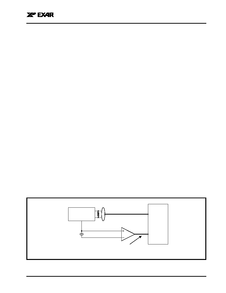
FIGURE 4. INPUT REFERENCED JITTER CONNECTION DIAGRAM
XRT8020
Channel 1
Channel 2
MAX9111ESA
Tektronix
TDS7404
Tektronix
P6330 Differential Probe
Tektronix
P6245 TDS 500/600
Outp
Outn
20.0Mhz
Crystal
相关PDF资料 |
PDF描述 |
|---|---|
| XRT91L31IQ | IC TXRX SONET/SDH 8BIT 64QFP |
| XRT91L33IG-F | IC MULTIRATE CDR 20TSSOP |
| XRT91L34IV-F | IC MULTIRATE CDR QUAD 128LQFP |
| 07010 | CALIBRATION UNIT NIST STD WS&FG |
| 07200 | CHAIR COVER STATSHIELD |
相关代理商/技术参数 |
参数描述 |
|---|---|
| XRT81L17IV-F | 功能描述:网络控制器与处理器 IC RoHS:否 制造商:Micrel 产品:Controller Area Network (CAN) 收发器数量: 数据速率: 电源电流(最大值):595 mA 最大工作温度:+ 85 C 安装风格:SMD/SMT 封装 / 箱体:PBGA-400 封装:Tray |
| XRT81L27 | 制造商:EXAR 制造商全称:EXAR 功能描述:SEVEN CHANNEL E1 LINE INTERFACE UNIT WITH CLOCK RECOVERY |
| XRT81L27IV | 功能描述:外围驱动器与原件 - PCI RoHS:否 制造商:PLX Technology 工作电源电压: 最大工作温度: 安装风格:SMD/SMT 封装 / 箱体:FCBGA-1156 封装:Tray |
| XRT81L27IV-F | 功能描述:外围驱动器与原件 - PCI RoHS:否 制造商:PLX Technology 工作电源电压: 最大工作温度: 安装风格:SMD/SMT 封装 / 箱体:FCBGA-1156 封装:Tray |
| XR-T8205CP | 制造商:未知厂家 制造商全称:未知厂家 功能描述:Telephone Ringer |
发布紧急采购,3分钟左右您将得到回复。