参数资料
| 型号: | ZL2008ALAFT1 |
| 厂商: | Intersil |
| 文件页数: | 15/42页 |
| 文件大小: | 0K |
| 描述: | IC REG CTRLR BUCK PWM VM 36-QFN |
| 标准包装: | 1,000 |
| PWM 型: | 电压模式 |
| 输出数: | 1 |
| 频率 - 最大: | 1.4MHz |
| 占空比: | 95% |
| 电源电压: | 3 V ~ 5.5 V |
| 降压: | 是 |
| 升压: | 无 |
| 回扫: | 无 |
| 反相: | 无 |
| 倍增器: | 无 |
| 除法器: | 无 |
| Cuk: | 无 |
| 隔离: | 无 |
| 工作温度: | -40°C ~ 85°C |
| 封装/外壳: | 36-VFQFN 裸露焊盘 |
| 包装: | 带卷 (TR) |
第1页第2页第3页第4页第5页第6页第7页第8页第9页第10页第11页第12页第13页第14页当前第15页第16页第17页第18页第19页第20页第21页第22页第23页第24页第25页第26页第27页第28页第29页第30页第31页第32页第33页第34页第35页第36页第37页第38页第39页第40页第41页第42页
�� �
�
�ZL2008�
�=�
�6900�
�R� SET�
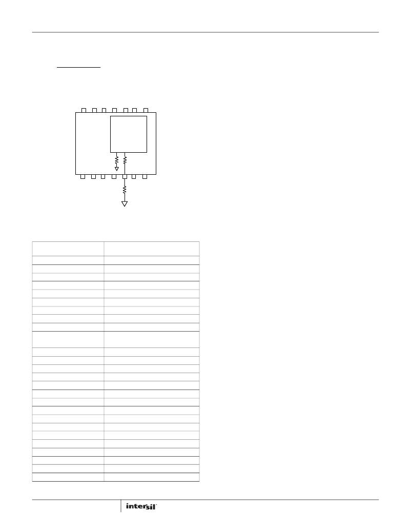
�DOSA� VOLTAGE� TRIM� MODE�
�On� a� DOSA� module,� the� V� OUT� setting� follows� Equation� 3:�
�(EQ.� 3)�
�V� OUT� ?� 0� .� 69� V�
�To� maintain� DOSA� compatibility,� the� same� scheme� is� used� as� with� a�
�POLA� module� except� the� 10k� Ω� resistor� is� replaced� with� a� 8.66k� Ω�
�resistor� as� shown� in� Figure� 12.�
�Start-up� Procedure�
�The� ZL2008� follows� a� specific� internal� start-up� procedure� after�
�power� is� applied� to� the� VDD� pin.� Table� 6� describes� the� start-up�
�sequence.�
�If� the� device� is� to� be� synchronized� to� an� external� clock� source,� the�
�clock� frequency� must� be� stable� prior� to� asserting� the� EN� pin.� The�
�device� requires� approximately� 5ms� to� 10ms� to� check� for� specific�
�values� stored� in� its� internal� memory.� If� the� user� has� stored� values�
�in� memory,� those� values� will� be� loaded.� The� device� will� then�
�check� the� status� of� all� multi-mode� pins� and� load� the� values�
�associated� with� the� pin� settings.�
�DOSA�
�MODULE�
�110� k� ?�
�ZL�
�V0� V1�
�8.66� k� ?�
�Once� this� process� is� completed,� the� device� is� ready� to� accept�
�commands� via� the� I� 2� C/SMBus� interface� and� the� device� is� ready�
�to� be� enabled.� Once� enabled,� the� device� requires� approximately�
�2ms� before� its� output� voltage� may� be� allowed� to� start� its� ramp-�
�up� process.� If� a� soft-start� delay� period� less� than� 2ms� has� been�
�configured� (using� PMBus� commands),� the� device� will� default� to� a�
�2ms� delay� period.� If� a� delay� period� greater� than� 2ms� is�
�Rset�
�FIGURE� 12.� R� SET� on� a� DOSA� Module�
�The� DOSA� mode� V� OUT� settings� are� listed� in� Table� 5.�
�TABLE� 5.� DOSA� Mode� V� OUT� Settings�
�configured,� the� device� will� wait� for� the� configured� delay� period�
�prior� to� starting� to� ramp� its� output.�
�After� the� delay� period� has� expired,� the� output� will� begin� to� ramp�
�towards� its� target� voltage� according� to� the� pre-configured�
�soft-start� ramp� time� that� has� been� set� using� the� SS� pin.� It� should�
�be� noted� that� if� the� EN� pin� is� tied� to� VDD,� the� device� will� still�
�require� approx� 5ms� to� 10ms� before� the� output� can� begin� its�
�V� OUT�
�(V)�
�0.700�
�0.752�
�0.758�
�0.765�
�0.772�
�0.790�
�0.800�
�0.821�
�0.834�
�0.848�
�0.880�
�0.899�
�0.919�
�0.965�
�0.991�
�1.000�
�1.100�
�1.158�
�1.200�
�1.250�
�1.500�
�1.669�
�1.800�
�2.295�
�2.506�
�3.300�
�5.000�
�R� SET� (k� Ω� )�
�In� series� with� 8.660k� Ω� resistor�
�162�
�113�
�100�
�90.9�
�82.5�
�75.0�
�57.6�
�52.3�
�47.5�
�43.2�
�36.5�
�33.2�
�30.1�
�25.5�
�22.6�
�21.0�
�17.8�
�14.7�
�13.3�
�10.5�
�8.87�
�6.98�
�6.04�
�4.32�
�3.74�
�2.61�
�1.50�
�ramp-up� as� described� in� Table� 6.�
�Soft-start� Delay� and� Ramp� Times�
�It� may� be� necessary� to� set� a� delay� from� when� an� enable� signal� is�
�received� until� the� output� voltage� starts� to� ramp� to� its� target�
�value.� In� addition,� the� designer� may� wish� to� precisely� set� the� time�
�required� for� V� OUT� to� ramp� to� its� target� value� after� the� delay� period�
�has� expired.� These� features� may� be� used� as� part� of� an� overall�
�inrush� current� management� strategy� or� to� precisely� control� how�
�fast� a� load� IC� is� turned� on.� The� ZL2008� gives� the� system� designer�
�several� options� for� precisely� and� independently� controlling� both�
�the� delay� and� ramp� time� periods.�
�The� soft-start� delay� period� begins� when� the� EN� pin� is� asserted�
�and� ends� when� the� delay� time� expires.� The� soft-start� delay� period�
�is� set� using� the� SS� pin.� Precise� ramp� delay� timing� reduces� the�
�delay� time� variations� but� is� only� available� when� the� appropriate�
�bit� in� the� MISC_CONFIG� register� has� been� set.� Please� refer� to�
�Application� Note� AN2033� for� details.�
�The� soft-start� ramp� timer� enables� a� precisely� controlled� ramp� to�
�the� nominal� V� OUT� value� that� begins� once� the� delay� period� has�
�expired.� The� ramp-up� is� guaranteed� monotonic� and� its� slope� may�
�be� precisely� set� using� the� SS� pin.�
�The� soft-start� delay� and� ramp� times� can� be� set� to� standard�
�values� according� to� Table� 7.�
�NOTE:� (R0� =� 110k� Ω� ,� R1� =� R� SET� +� 8.66k� Ω� )�
�15�
�FN6859.4�
�April� 29,� 2011�
�相关PDF资料 |
PDF描述 |
|---|---|
| ZL2101ALAFTK | IC REG BUCK SYNC ADJ 6A 36QFN |
| ZL2105ALNF | IC REG BUCK SYNC ADJ 3A 36QFN |
| ZL2106ALCNTK | IC REG BUCK SYNC ADJ 6A 36QFN |
| ZL6100ALAF | IC REG CTRLR BUCK PWM VM 36-QFN |
| ZL6105ALAFTR5546 | IC REG CTRLR BUCK PWM VM 36-QFN |
相关代理商/技术参数 |
参数描述 |
|---|---|
| ZL2008ALBFT | 功能描述:IC REG CTRLR BUCK PWM VM 36-QFN RoHS:是 类别:集成电路 (IC) >> PMIC - 稳压器 - DC DC 切换控制器 系列:- 产品培训模块:Lead (SnPb) Finish for COTS Obsolescence Mitigation Program 标准包装:2,500 系列:- PWM 型:电流模式 输出数:1 频率 - 最大:275kHz 占空比:50% 电源电压:18 V ~ 110 V 降压:无 升压:无 回扫:无 反相:无 倍增器:无 除法器:无 Cuk:无 隔离:是 工作温度:-40°C ~ 85°C 封装/外壳:8-SOIC(0.154",3.90mm 宽) 包装:带卷 (TR) |
| ZL2008ALBFT1 | 功能描述:IC REG CTRLR BUCK PWM VM 36-QFN RoHS:是 类别:集成电路 (IC) >> PMIC - 稳压器 - DC DC 切换控制器 系列:- 产品培训模块:Lead (SnPb) Finish for COTS Obsolescence Mitigation Program 标准包装:2,500 系列:- PWM 型:电流模式 输出数:1 频率 - 最大:275kHz 占空比:50% 电源电压:18 V ~ 110 V 降压:无 升压:无 回扫:无 反相:无 倍增器:无 除法器:无 Cuk:无 隔离:是 工作温度:-40°C ~ 85°C 封装/外壳:8-SOIC(0.154",3.90mm 宽) 包装:带卷 (TR) |
| ZL2008EVAL1Z | 功能描述:EVALUATION BOARD FOR ZL2008 RoHS:是 类别:编程器,开发系统 >> 评估板 - DC/DC 与 AC/DC(离线)SMPS 系列:- 产品培训模块:Obsolescence Mitigation Program 标准包装:1 系列:True Shutdown™ 主要目的:DC/DC,步升 输出及类型:1,非隔离 功率 - 输出:- 输出电压:- 电流 - 输出:1A 输入电压:2.5 V ~ 5.5 V 稳压器拓扑结构:升压 频率 - 开关:3MHz 板类型:完全填充 已供物品:板 已用 IC / 零件:MAX8969 |
| ZL20200 | 制造商:ZARLINK 制造商全称:Zarlink Semiconductor Inc 功能描述:Dual Band IS136/AMPS Transceiver |
| ZL20200_06 | 制造商:ZARLINK 制造商全称:Zarlink Semiconductor Inc 功能描述:Dual Band IS136/AMPS Transceiver |
发布紧急采购,3分钟左右您将得到回复。