参数资料
| 型号: | 20-101-1051 |
| 厂商: | Rabbit Semiconductor |
| 文件页数: | 68/164页 |
| 文件大小: | 0K |
| 描述: | MODULE RABBITCORE RCM3365 |
| 标准包装: | 1 |
| 系列: | RabbitCore® |
| 模块/板类型: | MPU 核心模块 |
| 适用于相关产品: | RCM3365 |
| 其它名称: | 316-1111 |
第1页第2页第3页第4页第5页第6页第7页第8页第9页第10页第11页第12页第13页第14页第15页第16页第17页第18页第19页第20页第21页第22页第23页第24页第25页第26页第27页第28页第29页第30页第31页第32页第33页第34页第35页第36页第37页第38页第39页第40页第41页第42页第43页第44页第45页第46页第47页第48页第49页第50页第51页第52页第53页第54页第55页第56页第57页第58页第59页第60页第61页第62页第63页第64页第65页第66页第67页当前第68页第69页第70页第71页第72页第73页第74页第75页第76页第77页第78页第79页第80页第81页第82页第83页第84页第85页第86页第87页第88页第89页第90页第91页第92页第93页第94页第95页第96页第97页第98页第99页第100页第101页第102页第103页第104页第105页第106页第107页第108页第109页第110页第111页第112页第113页第114页第115页第116页第117页第118页第119页第120页第121页第122页第123页第124页第125页第126页第127页第128页第129页第130页第131页第132页第133页第134页第135页第136页第137页第138页第139页第140页第141页第142页第143页第144页第145页第146页第147页第148页第149页第150页第151页第152页第153页第154页第155页第156页第157页第158页第159页第160页第161页第162页第163页第164页
10
RabbitCore RCM3365/RCM3375
2.2 Hardware Connections
There are three steps to connecting the Prototyping Board for use with Dynamic C and the
sample programs:
1. Attach the RCM3365/RCM3375 module to the Prototyping Board.
2. Connect the serial programming cable between the RCM3365/RCM3375 and the worksta-
tion PC or if you have an RCM3365 with RabbitSys firmware you may connect the
RCM3365 and the PC using Ethernet cables.
3. Connect the power supply to the Prototyping Board.
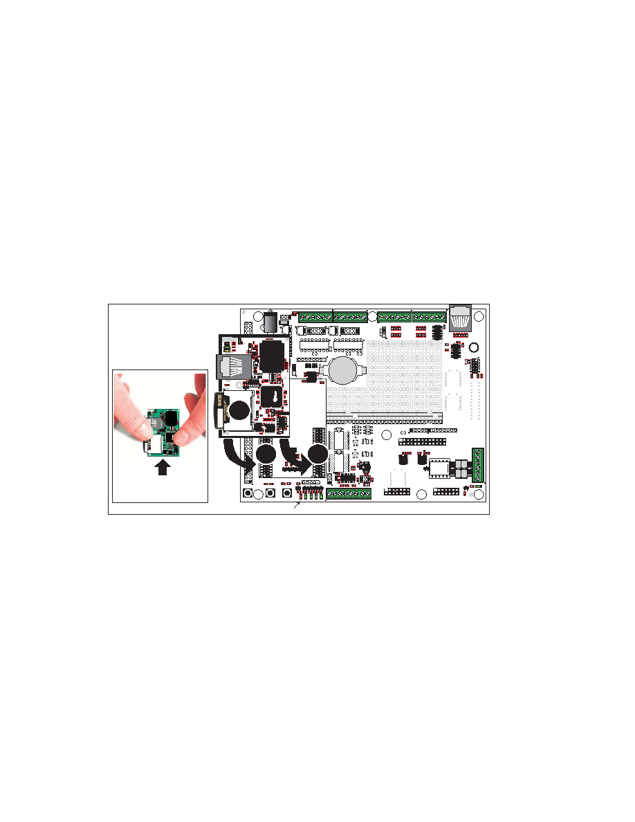
2.2.1 Step 1 — Attach Module to Prototyping Board
Turn the RCM3365/RCM3375 module so that the Ethernet jack is facing the direction shown
in Figure 2 below. Align the pins from headers J3 and J4 on the bottom side of the module into
header sockets JA and JB on the Prototyping Board. The picture card (NAND flash) does not
have to be inserted into connector J6 on the RCM3365/RCM3375 at this time.
Figure 2. Install the RCM3365/RCM3375 Module on the Prototyping Board
NOTE: It is important that you line up the pins on headers J3 and J4 of the RCM3365/
RCM3375 module exactly with the corresponding pins of header sockets JA and JB on
the Prototyping Board. The header pins may become bent or damaged if the pin align-
ment is offset, and the module will not work. Permanent electrical damage to the mod-
ule may also result if a misaligned module is powered up.
Press the module’s pins firmly into the Prototyping Board header sockets—press down in the
area above the header pins using your thumbs or fingers over the header pins as shown in
Figure 2. Do not press down on the picture card connector (J6) unless the picture card is
installed, but rather press down on the circuit board along the edge by the connector. Also, do
not press down on the middle of the module to avoid flexing the module, which could damage
the module or components on the module.
Should you need to remove the module, grasp it with your fingers along the sides by the con-
nectors and gently work the module up to pull the pins away from the sockets where they are
installed. Do not remove the module by grasping it at the top and bottom.
+BKL
T
/CS
LED1
LED3
LED5
GND
A2
A0
D1
D3
D5
D7
RABBITNET
R44
C28
C27
R43
R46
C30
C29
R45
Q5
R48
R47
DS7 RELA
Y
NO1
COM1
NC1
NO2
COM2
NC2
K1
KEYPAD DISPLAY BOARD
D8
LCD1JB
LCD1JC
+V
/RES
LED0
LED2
LED4
LED6
GND
A3
A1
D0
D2
D4
D6
LCD1JA
J16
BD0
BD1
BD2
BD3
BD4
BD5
BD6
BD7
J15
BA0
BA1
BA2
BA3
LCD /CS
RELA
Y
RA
TED
0.5
A
@
30
V
J17
U12
U11
R42
R41
C20
C19
R40
R39
SERIAL
FLASH/
MODEM
J7
R2
R7
R3 R4 R5 R6
R9
R8 U6
R10
C6
C1
D1
J2
J1
J4
J6
GND
IN3
IN2
IN1
IN0
+5V
QD2AQD2B
QD1AQD1B
GN
D
J5
VMBMDB1
MDB2MDB3
MDB4VMB+
VMA+MDA1
MDA2MDA3
MDA4VMA
J3
C2
JP1
C3
JP2
GND
VBT
/RES
SM0
/IOWR
PG5
PG7
PE1
PE4
PE6
PF7
PF5
PB7
PB5
PB3
PB0
J8
NC
+3.3 V
VRAM
SMODE1
/IORD
PG4
PG6
PE0
PE3
PE5
PB6
PB4
PB2
/RES_OUT
PF4
PF6
PE7
RCM3300
PROTOTYPING
BOARD
S1
RESET
J9
S2
S3
ACT
PD7
PD3
PD5
PG3
PG1
PC7
PC5
PC3
PC1
PF0
PF2
PA0
PA2
PA4
PA6
STAT
LINK
PD6
PD2
PD4
PG2
PG0
PC6
PC4
PC2
PC0
PF1
PF3
PA1
PA3
PA5
PA7
GND
JA
JB
POWER
GND
+DC
GND
DS1
R1
GND
+DC
D2
C8
L1
R1
1
JP3
R12
C9
C10 C1
1
C12
JP4
J10
RP1 RP2
R14
C5
BT1
C13
U5
R16
R15
R17
00 01 02 03 04 05 06 07
OUT
C4
R13
U1
U2
L293D
H-DRIVER
L293D
H-DRIVER
U8
R25 R26
R27 R28
J14
C24
U10
R38
R37
R35
C26
JP5
R36
C23
C21
U9
C22
J13
R33 R34
C17
C18
UX5
UX1
SO20W
UX2
SO20W
DX2
C25
J12
R50
Q6
R49
D4 D5 D6 D7
GND
HO4
HO3
HO2
HO1
R29
R30
R31
R32
CORE
DS2 DS3 DS4 DS5 DS6
TxE RxE GND TxF RxF 485+ GND 485
Q1 Q2 Q3 Q4
C16
R24
R23
R22
R21
CORE MODULE
GND/EGND
U4
GND
+3.3 V
+5 V
+3.3 V
+5 V
U3
UX4
DX1
RX16
RX17
RX13
RX14
RX18
RX15
PF0_CLKD
PF0_QD
J11
C7
U7
R18
R19
R20
C14 C15
CX1
CX2
R55 R56 R57 R58
R63 R64 R65 R66
R59
R62
R60 R61
R52 R53
R51
R54
SOT23-6
R67
R68
R69
R70
DS2
R35
R36
R37
R38
R43
DS4
U13
C81
C78
C74
R1
R14
R15
R26
R27
R13
U2
R12
R1
1
J1
R10
C1
C6
R8
C10
C11
C15
C19
C20
C24
C28
R17
C35
C77
R79
C72
C70
C71
C80
C82
R31
R53
R54
R44
C58
C34
R20
R21C36
R25
C27
C21
C18
C12
C13
C9
U3
R7
C2
C3
R6
Y1
R9
R84
C4
R2
R5
U1
C5
R80
R85R70
R86
R64R77
R50
R29
JP9
R59
C104
U5
C67
R45
C14
U6
R19
U4
R18
R22
JP6
JP7
JP8
JP4
JP5
C22
J6
L4
C79
L1
C42
R81
C86
C76
J2
R30
R82
Y2
Q2
R96
R67
C105
DS3
USR
FM
LINK
ACT
DS1
C61
SPEED
R23
U16
R4
L2
CORE LED
RCM3365/
RCM3375
J6
Do not press down
here.
JB
JA
相关PDF资料 |
PDF描述 |
|---|---|
| 305-030-520-204 | CONN CARDEDGE 30POS .156 GREEN |
| 20-101-1196 | MODULE RABBITCORE RCM3900 |
| 20-101-1105 | MODULE RCM4100 RABBITCORE |
| 20-101-1028 | MODULE RABBITCORE RCM3750 |
| 046232104015800+ | CONN FFC/FPC 4POS 1MM VERT SMD |
相关代理商/技术参数 |
参数描述 |
|---|---|
| 20-101-1055 | 功能描述:模块化系统 - SOM RCM3375 RABBITCORE RoHS:否 制造商:Digi International 外观尺寸:ConnectCore 9P 处理器类型:ARM926EJ-S 频率:150 MHz 存储容量:8 MB, 16 MB 存储类型:NOR Flash, SDRAM 接口类型:I2C, SPI, UART 工作电源电压:3.3 V 最大工作温度:+ 85 C 尺寸:1.97 in x 1.97 in x 6.1 in |
| 20-101-1066 | 功能描述:模块化系统 - SOM RCM3720 PROTO RS232 RoHS:否 制造商:Digi International 外观尺寸:ConnectCore 9P 处理器类型:ARM926EJ-S 频率:150 MHz 存储容量:8 MB, 16 MB 存储类型:NOR Flash, SDRAM 接口类型:I2C, SPI, UART 工作电源电压:3.3 V 最大工作温度:+ 85 C 尺寸:1.97 in x 1.97 in x 6.1 in |
| 20-101-1067 | 功能描述:模块化系统 - SOM RCM3305 MODULE RoHS:否 制造商:Digi International 外观尺寸:ConnectCore 9P 处理器类型:ARM926EJ-S 频率:150 MHz 存储容量:8 MB, 16 MB 存储类型:NOR Flash, SDRAM 接口类型:I2C, SPI, UART 工作电源电压:3.3 V 最大工作温度:+ 85 C 尺寸:1.97 in x 1.97 in x 6.1 in |
| 20-101-1068 | 功能描述:模块化系统 - SOM RCM3315 MODULE RoHS:否 制造商:Digi International 外观尺寸:ConnectCore 9P 处理器类型:ARM926EJ-S 频率:150 MHz 存储容量:8 MB, 16 MB 存储类型:NOR Flash, SDRAM 接口类型:I2C, SPI, UART 工作电源电压:3.3 V 最大工作温度:+ 85 C 尺寸:1.97 in x 1.97 in x 6.1 in |
| 20-101-1087 | 制造商:Digi International 功能描述:RCM3365 RABBITSYS - Bulk 制造商:Digi International Inc 功能描述:BOARD PROTO RCM3365 RS232 制造商:Rabbit Semiconductor 功能描述:RCM3365 Rabbit Sys |
发布紧急采购,3分钟左右您将得到回复。