- 您现在的位置:买卖IC网 > PDF目录373890 > AD6622AS (ANALOG DEVICES INC) Four-Channel, 75 MSPS Digital Transmit Signal Processor TSP PDF资料下载
参数资料
| 型号: | AD6622AS |
| 厂商: | ANALOG DEVICES INC |
| 元件分类: | 通信及网络 |
| 英文描述: | Four-Channel, 75 MSPS Digital Transmit Signal Processor TSP |
| 中文描述: | SPECIALTY TELECOM CIRCUIT, PQFP128 |
| 封装: | METRIC, QFP-128 |
| 文件页数: | 19/28页 |
| 文件大小: | 242K |
| 代理商: | AD6622AS |
第1页第2页第3页第4页第5页第6页第7页第8页第9页第10页第11页第12页第13页第14页第15页第16页第17页第18页当前第19页第20页第21页第22页第23页第24页第25页第26页第27页第28页
AD6622
–19–
REV. 0
1. Write the NCO Freq Hold-Off (0x03) Counter to the appro-
priate value (greater than 1 and less then 2
16
–
1).
2. Write the NCO Frequency Register(s) to the new desired
frequency.
3. Write the hop bit and the sync(s) bit high (Ext Address 5).
4. This starts the NCO Freq Hold-Off Counter counting down.
The counter is clocked with the AD6622 CLK signal. When
it reaches a count of one, the new frequency is loaded into
the NCO.
Hop with Pin Sync
A sync pin is provided on the AD6622 to provide the most
accurate synchronization, especially between multiple AD6622s.
Synchronization of hopping to a new NCO frequency with an
external signal is accomplished with the following method.
1. Write the NCO Freq Hold-Off Counter(s) (0x03) to the
appropriate value (greater than 1 and less than 2
16
–
1).
2. Write the NCO Frequency register(s) to the new desired
frequency.
3. Set the hop on pin sync bit and the appropriate sync pin
enable high (0x001).
4. When the sync pin is sampled high by the AD6622 CLK this
enables the countdown of the NCO Freq Hold-Off Counter.
The counter is clocked with the AD6622 CLK signal. When
it reaches a count of one the new frequency is loaded into the
NCO.
Beam is a change in phase for a particular channel and can be
synchronized with respect to other channels or AD6622s. This
change in phase can be synchronized via microprocessor control
or an external sync signal as described below.
To set the amplitude without synchronization the following
method should be used.
Set Phase No Beam
1. Set the NCO Phase Offset Update Hold-Off Counter (0x05)
to 0.
2. Load the appropriate NCO Phase Offset (0x04). The NCO
Phase Offset will be immediately loaded.
Beam with Soft Sync
The AD6622 includes the ability to synchronize a change in
NCO phase of multiple channels or chips under microprocessor
control. The NCO Phase Offset Update Hold-Off Counter, in
conjunction with the beam bit and the sync bit (Ext Address 5),
allow this synchronization. Basically the NCO Phase Offset
Update Hold-Off Counter delays the new phase from being
loaded into the NCO/RCF by its value (number of AD6622
CLKs). The following method is used to synchronize a beam-in
phase of multiple channels via microprocessor control.
1. Write the NCO Phase offset Update Hold-Off Counter (0x05)
to the appropriate value (greater than 1 and less then 2
16
–
1).
2. Write the NCO Phase Offset Register(s) to the new desired
phase and amplitude.
3. Write the beam bit and the sync(s) bit high (External
Address 5).
4. This starts the NCO Phase Offset Update Hold-Off counter
counting down. The counter is clocked with the AD6622
CLK signal. When it reaches a count of one, the new phase
is loaded into the NCO.
Beam with Pin Sync
A sync pin is provided on the AD6622 to provide the most
accurate synchronization, especially between multiple AD6622s.
Synchronization of beaming to a new NCO Phase Offset with an
external signal is accomplished with the following method.
1. Write the NCO Phase Offset Hold-Off (0x05) counter(s) to
the appropriate value (greater than 1 and less than 2
16
–
1).
2. Write the NCO Phase Offset register(s) to the new desired
phase and amplitude.
3. Set the beam on pin sync bit and the appropriate sync pin
enable high (0x001).
4. When the sync pin is sampled high by the AD6622 CLK, it
enables the countdown of the NCO Phase Offset Hold-Off
Counter. The counter is clocked with the AD6622 CLK sig-
nal. When it reaches a count of one, the new phase is loaded
into the NCO registers.
JTAG INTERFACE
The AD6622 supports a subset of IEEE Standard 1149.1
speci
fi
cations. For additional details of the standard, please
see
“
IEEE Standard Test Access Port and Boundary-Scan
Architecture,
”
IEEE-1149 publication from IEEE.
The AD6622 has
fi
ve pins associated with the JTAG interface.
These pins are used to access the on-chip Test Access Port and
are listed in Table VIII.
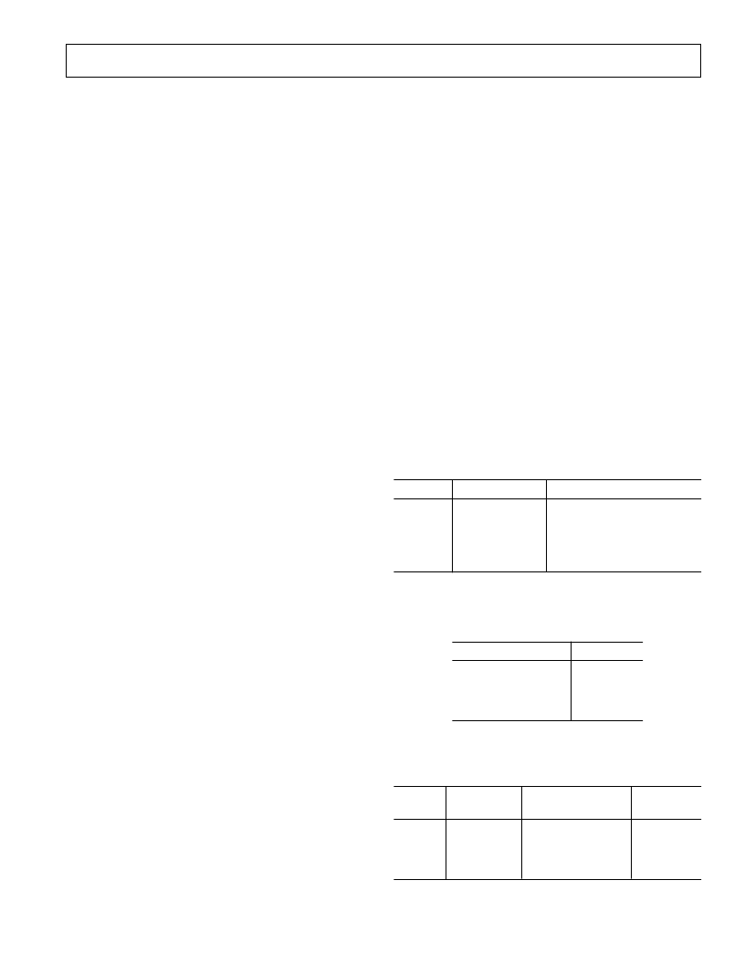
Table VIII. JTAG Pin List
Name
Pin Number
Description
TRST
TCK
TMS
TDI
TDO
100
101
106
108
107
Test Access Port Reset
Test Clock
Test Access Port Mode Select
Test Data Input
Test Data Output
The AD6622 supports four op codes as shown in Table IX.
These instructions set the mode of the JTAG interface.
Table IX. JTAG Op Codes
Instruction
Op Code
IDCODE
BYPASS
SAMPLE/PRELOAD
EXTEST
10
11
01
00
The Vendor Identi
fi
cation Code can be accessed through the
IDCODE instruction and has the following format.
Table X. JTAG ID String
MSB
Version
Part
Number
Manufacturing
ID #
LSB
Mandatory
000
0010
0111
1000
0000
000 1110 0101
1
A BSDL
fi
le for this device is available from Analog Devices, Inc.
Contact Analog Devices Inc. for more information.
相关PDF资料 |
PDF描述 |
|---|---|
| AD6622PCB | Four-Channel, 75 MSPS Digital Transmit Signal Processor TSP |
| AD6622S | Four-Channel, 75 MSPS Digital Transmit Signal Processor TSP |
| AD6622 | Four-Channel, 75 MSPS Digital Transmit Signal Processor TSP |
| AD6623 | 4-Channel, 104 MSPS Digital Transmit Signal Processor TSP |
| AD6623ABC | 4-Channel, 104 MSPS Digital Transmit Signal Processor TSP |
相关代理商/技术参数 |
参数描述 |
|---|---|
| AD6622PCB | 制造商:AD 制造商全称:Analog Devices 功能描述:Four-Channel, 75 MSPS Digital Transmit Signal Processor TSP |
| AD6622S | 制造商:AD 制造商全称:Analog Devices 功能描述:Four-Channel, 75 MSPS Digital Transmit Signal Processor TSP |
| AD6622S/PCB | 制造商:AD 制造商全称:Analog Devices 功能描述:Four-Channel, 75 MSPS Digital Transmit Signal Processor TSP |
| AD6623 | 制造商:Analog Devices 功能描述: |
| AD6623ABC | 制造商:Analog Devices 功能描述:Signal Processor 196-Pin CSP-BGA 制造商:Rochester Electronics LLC 功能描述:4 CHANNEL, 104 MSPS DIGITAL TSP - Bulk |
发布紧急采购,3分钟左右您将得到回复。