- 您现在的位置:买卖IC网 > PDF目录10245 > AD7739BRUZ-REEL7 (Analog Devices Inc)IC ADC 24BIT 8CH SIG-DEL 24TSSOP PDF资料下载
参数资料
| 型号: | AD7739BRUZ-REEL7 |
| 厂商: | Analog Devices Inc |
| 文件页数: | 11/32页 |
| 文件大小: | 0K |
| 描述: | IC ADC 24BIT 8CH SIG-DEL 24TSSOP |
| 标准包装: | 1,000 |
| 位数: | 24 |
| 采样率(每秒): | 15.1k |
| 数据接口: | DSP,MICROWIRE?,QSPI?,串行,SPI? |
| 转换器数目: | 1 |
| 功率耗散(最大): | 100mW |
| 电压电源: | 模拟和数字 |
| 工作温度: | -40°C ~ 105°C |
| 安装类型: | 表面贴装 |
| 封装/外壳: | 24-TSSOP(0.173",4.40mm 宽) |
| 供应商设备封装: | 24-TSSOP |
| 包装: | 带卷 (TR) |
| 输入数目和类型: | 8 个单端,单极;8 个单端,双极;4 个差分,单极;4 个差分,双极 |
| 配用: | EVAL-AD7739EBZ-ND - BOARD EVAL FOR AD7739 |
第1页第2页第3页第4页第5页第6页第7页第8页第9页第10页当前第11页第12页第13页第14页第15页第16页第17页第18页第19页第20页第21页第22页第23页第24页第25页第26页第27页第28页第29页第30页第31页第32页
Data Sheet
AD7739
Rev. A | Page 19 of 32
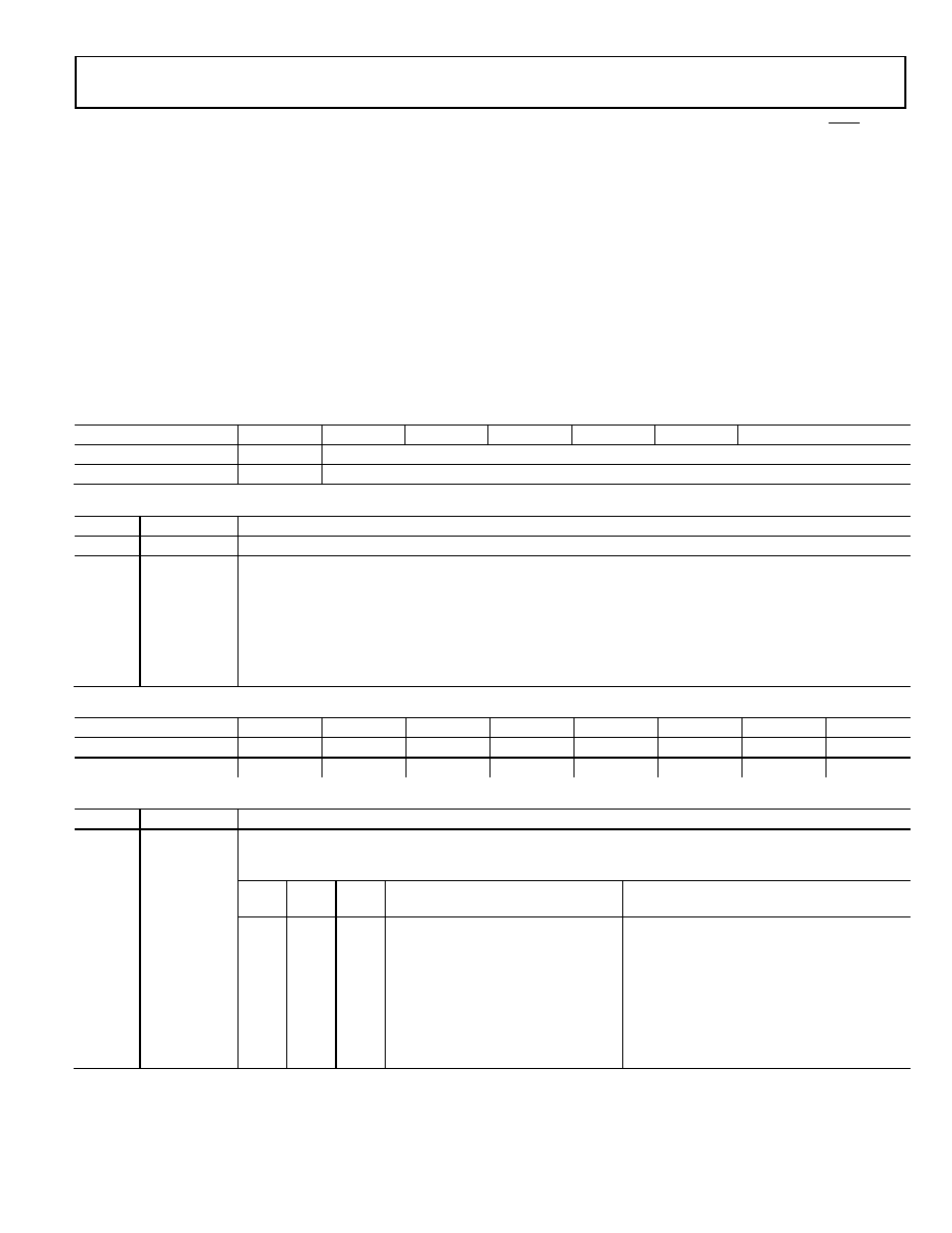
CHANNEL CONVERSION TIME REGISTERS
8 Bits, Read/Write Registers, Address 0x30 to
Address 0x37, Default Value 0x91
The conversion time registers enable or disable chopping and
configure the digital filter for a particular channel (see Table 25
and Table 26). This register value affects the conversion time,
frequency response, and noise performance of the ADC.
MODE REGISTER
8 Bits, Read/Write Register, Address 0x38 to
Address 0x3F, Default Value 0x00
The mode register configures the part and determines its operating
mode (see Table 27, Table 28, and Table 29). Writing to the
mode register clears the ADC status register, sets the RDY pin
to a logic high level, exits all current operations, and starts the
mode specified by the mode bits.
The AD7739 contains only one mode register. The two LSBs of
the address are used for writing to the mode register to specify
the channel selected for the operation determined by the MD2
to MD0 bits. Only the address 0x38 must be used for reading
from the mode register.
Table 25. Channel Conversion Time Registers Bits
Bit
Bit 7
Bit 6
Bit 5
Bit 4
Bit 3
Bit 2
Bit 1
Bit 0
Mnemonic
Chop
FW (7-bit filter word)
Default
1
0x11
Table 26. Channel Conversion Time Registers Bit Descriptions
Bit
Mnemonic
Description
7
Chop
Chopping enable bit. Set to 1 to apply chopping mode for a particular channel.
6 to 0
FW
Chop = 1, single conversion or continuous conversion with one channel enabled.
Conversion Time (s) = (FW × 128 + 262)/MCLK Frequency (MHz), the FW range is 2 to 127.
Chop = 1, continuous conversion with two or more channels enabled.
Conversion Time (s) = (FW × 128 + 263)/MCLK Frequency (MHz), the FW range is 2 to 127.
Chop = 0, single conversion or continuous conversion with one channel enabled.
Conversion Time (s) = (FW × 64 + 213)/MCLK Frequency (MHz), the FW range is 3 to 127.
Chop = 0, continuous conversion with two or more channels enabled.
Conversion Time (s) = (FW × 64 + 214)/MCLK Frequency (MHz), the FW range is 3 to 127.
Table 27. Mode Register Bits
Bit
Bit 7
Bit 6
Bit 5
Bit 4
Bit 3
Bit 2
Bit 1
Bit 0
Mnemonic
MD2
MD1
MD0
CLKDIS
Dump
Cont RD
24/16 BIT
Clamp
Default
0
Table 28. Mode Register Bit Descriptions
Bit
Mnemonic
Description
7 to 5
MD2 to MD0
Mode bits. These three bits determine the AD7739 operation mode. Writing a new value to the mode bits exit
the part from the mode in which it has been operating and place it in the newly requested mode immediately.
The function of the mode bits follows.
MD2
MD1
MD0
Mode
Address Used for Mode Register Write
Specifies
0
Idle
0
1
Continuous conversion
First channel to start converting
0
1
0
Single conversion
Channel to convert
0
1
Power-down (standby)
1
0
ADC zero-scale self-calibration
Conversion time for calibration
1
0
1
ADC full-scale self-calibration (for 2.5 V)
Conversion time for calibration
1
0
Channel zero-scale system calibration
Channel to calibrate
1
Channel full-scale system calibration
Channel to calibrate
相关PDF资料 |
PDF描述 |
|---|---|
| AD9223ARSZ-REEL | IC ADC 12BIT 3.0MSPS 28SSOP |
| AD9221ARSZ-REEL | IC ADC 12BIT 1.5MSPS 28SSOP |
| MS3106E22-22P | CONN PLUG 4POS STRAIGHT W/PINS |
| LTC1418IG#TRPBF | IC A/D CONV 14BIT SRL&PAR 28SSOP |
| D38999/20WD5PA | CONN RCPT 5POS WALL MNT W/PINS |
相关代理商/技术参数 |
参数描述 |
|---|---|
| AD773A | 制造商:AD 制造商全称:Analog Devices 功能描述:10-Bit, 20 MSPS Monolithic A/D Converter |
| AD773AJD | 制造商:Analog Devices 功能描述:ADC Single Pipelined 20Msps 10-bit Parallel 28-Pin CDIP 制造商:Rochester Electronics LLC 功能描述:IC, 10-BIT 20 MSPS ADC - Bulk |
| AD773AKD | 制造商:AD 制造商全称:Analog Devices 功能描述:10-Bit, 20 MSPS Monolithic A/D Converter |
| AD773ASD/883B | 制造商:未知厂家 制造商全称:未知厂家 功能描述:Analog-to-Digital Converter, 10-Bit |
| AD773-EB | 制造商:Rochester Electronics LLC 功能描述:- Bulk |
发布紧急采购,3分钟左右您将得到回复。