- 您现在的位置:买卖IC网 > PDF目录10245 > AD7739BRUZ-REEL7 (Analog Devices Inc)IC ADC 24BIT 8CH SIG-DEL 24TSSOP PDF资料下载
参数资料
| 型号: | AD7739BRUZ-REEL7 |
| 厂商: | Analog Devices Inc |
| 文件页数: | 16/32页 |
| 文件大小: | 0K |
| 描述: | IC ADC 24BIT 8CH SIG-DEL 24TSSOP |
| 标准包装: | 1,000 |
| 位数: | 24 |
| 采样率(每秒): | 15.1k |
| 数据接口: | DSP,MICROWIRE?,QSPI?,串行,SPI? |
| 转换器数目: | 1 |
| 功率耗散(最大): | 100mW |
| 电压电源: | 模拟和数字 |
| 工作温度: | -40°C ~ 105°C |
| 安装类型: | 表面贴装 |
| 封装/外壳: | 24-TSSOP(0.173",4.40mm 宽) |
| 供应商设备封装: | 24-TSSOP |
| 包装: | 带卷 (TR) |
| 输入数目和类型: | 8 个单端,单极;8 个单端,双极;4 个差分,单极;4 个差分,双极 |
| 配用: | EVAL-AD7739EBZ-ND - BOARD EVAL FOR AD7739 |
第1页第2页第3页第4页第5页第6页第7页第8页第9页第10页第11页第12页第13页第14页第15页当前第16页第17页第18页第19页第20页第21页第22页第23页第24页第25页第26页第27页第28页第29页第30页第31页第32页
Data Sheet
AD7739
Rev. A | Page 23 of 32
CONTINUOUS CONVERSION MODE
When the mode register is being written, the ADC status byte is
cleared and the RDY pin goes high, regardless of its previous
state. When the continuous conversion command is written to
the mode register, the ADC starts conversion on the channel
selected by the address of the mode register.
After the conversion is complete, the relevant channel data
register and channel status register are updated, the relevant
RDY bit in the ADC status register is set, and the AD7739
continues converting on the next enabled channel. The part
cycles through all enabled channels until put into another mode
or reset. The cycle period is the sum of all conversion times of
enabled channels, set by the corresponding channel conversion
time registers.
The RDY bit is reset when the relevant channel data register is
being read. The behavior of the RDY pin depends on the
RDYFN bit in the I/O port register. When the RDYFN bit is 0,
the RDY pin goes low when any channel has unread data. When
the RDYFN bit is set to 1, the RDY pin goes low only if all
enabled channels have unread data.
If an ADC conversion result is not read before a new ADC
conversion is completed, the new result overwrites the previous
one. The relevant RDY bit goes low and the RDY pin goes high
for at least 163 MCLK cycles (~26.5 s), indicating when the data
register is updated, and the previous conversion data is lost.
If the data register is being read as an ADC conversion completes,
the data register is not updated with the new result (to avoid
data corruption) and the new conversion data is lost.
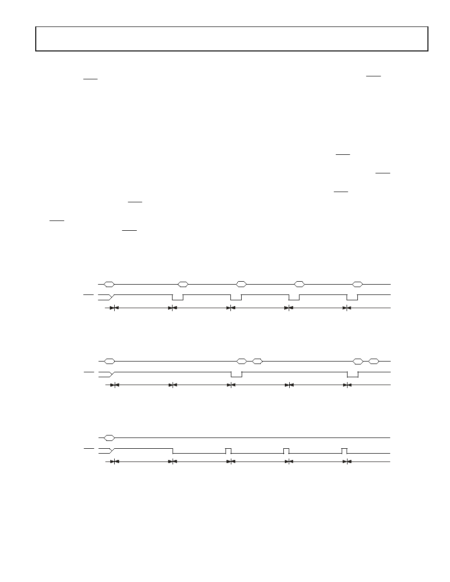
Figure 18 shows the sequence of the digital interface signal for
the continuous conversion mode with Channels 0 and 1 enabled
and the RDYFN bit set to 0. The RDY pin goes low and the data
register is read after each conversion. Figure 19 shows a similar
sequence but with the RDYFN bit set to 1. The RDY pin goes
low and all data registers are read after all conversions are
completed. Figure 20 shows the RDY pin when no data is read
from the AD7739.
Figure 18. Continuous Conversion, CH0 and CH1, RDYFN = 0
Figure 19. Continuous Conversion, CH0 and CH1, RDYFN = 1
Figure 20. Continuous Conversion, CH0 and CH1, No Data Read
SERIAL
INTERFACE
START
CONTINUOUS
CONVERSION
RDY
CH0 CONVERSION
READ
DATA
CH1
CH1 CONVERSION
CH0 CONVERSION
READ
DATA
CH0
CH1 CONVERSION
READ
DATA
CH0
CH0 CONVERSION
READ
DATA
CH1
03742-0-019
SERIAL
INTERFACE
START
CONTINUOUS
CONVERSION
RDY
CH0 CONVERSION
READ
DATA
CH1
CH1 CONVERSION
CH0 CONVERSION
READ
DATA
CH0
CH1 CONVERSION
READ
DATA
CH0
CH0 CONVERSION
READ
DATA
CH1
03742-0-020
SERIAL
INTERFACE
START
CONTINUOUS
CONVERSION
RDY
CH0 CONVERSION
CH1 CONVERSION
CH0 CONVERSION
CH1 CONVERSION
CH0 CONVERSION
03742-0-021
相关PDF资料 |
PDF描述 |
|---|---|
| AD9223ARSZ-REEL | IC ADC 12BIT 3.0MSPS 28SSOP |
| AD9221ARSZ-REEL | IC ADC 12BIT 1.5MSPS 28SSOP |
| MS3106E22-22P | CONN PLUG 4POS STRAIGHT W/PINS |
| LTC1418IG#TRPBF | IC A/D CONV 14BIT SRL&PAR 28SSOP |
| D38999/20WD5PA | CONN RCPT 5POS WALL MNT W/PINS |
相关代理商/技术参数 |
参数描述 |
|---|---|
| AD773A | 制造商:AD 制造商全称:Analog Devices 功能描述:10-Bit, 20 MSPS Monolithic A/D Converter |
| AD773AJD | 制造商:Analog Devices 功能描述:ADC Single Pipelined 20Msps 10-bit Parallel 28-Pin CDIP 制造商:Rochester Electronics LLC 功能描述:IC, 10-BIT 20 MSPS ADC - Bulk |
| AD773AKD | 制造商:AD 制造商全称:Analog Devices 功能描述:10-Bit, 20 MSPS Monolithic A/D Converter |
| AD773ASD/883B | 制造商:未知厂家 制造商全称:未知厂家 功能描述:Analog-to-Digital Converter, 10-Bit |
| AD773-EB | 制造商:Rochester Electronics LLC 功能描述:- Bulk |
发布紧急采购,3分钟左右您将得到回复。