- 您现在的位置:买卖IC网 > PDF目录10218 > AD7856ARSZ-REEL7 (Analog Devices Inc)IC ADC 14BIT 8CHAN 5V 24SSOP PDF资料下载
参数资料
| 型号: | AD7856ARSZ-REEL7 |
| 厂商: | Analog Devices Inc |
| 文件页数: | 10/32页 |
| 文件大小: | 0K |
| 描述: | IC ADC 14BIT 8CHAN 5V 24SSOP |
| 标准包装: | 500 |
| 位数: | 14 |
| 采样率(每秒): | 285k |
| 数据接口: | 8051,QSPI?,串行,SPI? µP |
| 转换器数目: | 2 |
| 功率耗散(最大): | 89.25mW |
| 电压电源: | 模拟和数字 |
| 工作温度: | -40°C ~ 105°C |
| 安装类型: | 表面贴装 |
| 封装/外壳: | 24-SSOP(0.209",5.30mm 宽) |
| 供应商设备封装: | 24-SSOP |
| 包装: | 带卷 (TR) |
| 输入数目和类型: | 8 个单端,单极;4 个伪差分,单极 |
第1页第2页第3页第4页第5页第6页第7页第8页第9页当前第10页第11页第12页第13页第14页第15页第16页第17页第18页第19页第20页第21页第22页第23页第24页第25页第26页第27页第28页第29页第30页第31页第32页
AD7856
–18–
REV. A
PERFORMANCE CURVES
The following performance curves apply to Mode 2 operation
only. If a conversion is initiated in software, then a slight degra-
dation in SNR can be expected when in Mode 2 operation. As
the sampling instant cannot be guaranteed internally, nonequi-
distant sampling will occur, resulting in a rise in the noise floor.
Initiating conversions in software is not recommended for Mode
1 operation.
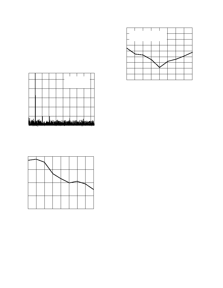
Figure 18 shows a typical FFT plot for the AD7856 at 190 kHz
sample rate and 10 kHz input frequency.
FREQUENCY –kHz
–115
010
–95
–75
–55
–35
–15
20
30
40
50
60
70
80
90
4096 POINT FFT
FSAMPLE = 190.476 kHz
FIN = 10.091 kHz
SNR = 79.2dB
Figure 18. FFT Plot
Figure 19 shows the SNR vs. Frequency for 5 V supply and a
4.096 external reference (5 V reference is typically 1 dB better
performance).
INPUT FREQUENCY – kHz
79
75
0
166
20
50
120
140
78
77
76
S(N+D)
RATIO
–
dB
10
80
100
Figure 19. SNR vs. Frequency
Figure 20 shows the Power Supply Rejection Ratio versus Fre-
quency for the part. The Power Supply Rejection Ratio is de-
fined as the ratio of the power in ADC output at frequency f to
the power of a full-scale sine wave.
PSRR (dB) = 10 log (Pf/Pfs)
Pf = Power at frequency f in ADC output, Pfs = power of a
full-scale sine wave. Here a 100 mV peak-to-peak sine wave is
coupled onto the AVDD supply while the digital supply is left
unaltered.
INPUT FREQUENCY – kHz
–72
–74
–90
0.91
100
13.4
25.7
38.3
50.3
–76
–78
–80
–88
PSRR
–
dB
–82
–84
–86
63.5
74.8
87.4
AVDD = DVDD = 5.0V
100mV p-p SINEWAVE ON AVDD
REFIN = 4.098 EXT REFERENCE
Figure 20. PSRR vs. Frequency
POWER-DOWN OPTIONS
The AD7856 provides flexible power management to allow the
user to achieve the best power performance for a given through-
put rate. The power management options are selected by
programming the power management bits, PMGT1 and PMGT0,
in the control register and by use of the
SLEEP pin. Table VI
summarizes the power-down options that are available and how
they can be selected by using either software, hardware or a
combination of both. The AD7856 can be fully or partially
powered down. When fully powered down, all the on-chip cir-
cuitry is powered down and IDD is 1
A typ. If a partial power-
down is selected, then all the on-chip circuitry except the reference
is powered down and IDD is 400 A typ. The choice of full or par-
tial power-down does not give any significant improvement in
throughput with a power-down between conversions. This is
discussed in the next section–Power-Up Times. However, a
partial power-down does allow the on-chip reference to be used
externally even though the rest of the AD7856 circuitry is pow-
ered down. It also allows the AD7856 to be powered up faster
after a long power-down period when using the on-chip refer-
ence (See Power-Up Times–Using On-Chip Reference).
When using the
SLEEP pin, the power management bits PMGT1
and PMGT0 should be set to zero (default status on power-up).
Bringing the
SLEEP pin logic high ensures normal operation,
and the part does not power down at any stage. This may be
necessary if the part is being used at high throughput rates when
it is not possible to power down between conversions. If the user
wishes to power down between conversions at lower throughput
rates (i.e. <100 kSPS for the AD7856) to achieve better power
performances, then the
SLEEP pin should be tied logic low.
If the power-down options are to be selected in software only,
then the
SLEEP pin should be tied logic high. By setting the
power management bits PMGT1 and PMGT0 as shown in
Table VI, a Full Power-Down, Full Power-Up, Full Power-
Down Between Conversions, and a Partial Power-Down Be-
tween Conversions can be selected.
相关PDF资料 |
PDF描述 |
|---|---|
| VI-21J-IU-F3 | CONVERTER MOD DC/DC 36V 200W |
| CS8416-CNZ | IC RCVR DGTL 192KHZ 28QFN COMM |
| VI-21J-IU-F2 | CONVERTER MOD DC/DC 36V 200W |
| SP3494EN-L/TR | IC TXRX RS485/RS422 LP 8NSOIC |
| SP3491EN-L/TR | IC TXRX RS485 FULL DUPLX 14NSOIC |
相关代理商/技术参数 |
参数描述 |
|---|---|
| AD7856ARZ | 功能描述:IC ADC 14BIT 8CHAN 5V 24SOIC RoHS:是 类别:集成电路 (IC) >> 数据采集 - 模数转换器 系列:- 其它有关文件:TSA1204 View All Specifications 标准包装:1 系列:- 位数:12 采样率(每秒):20M 数据接口:并联 转换器数目:2 功率耗散(最大):155mW 电压电源:模拟和数字 工作温度:-40°C ~ 85°C 安装类型:表面贴装 封装/外壳:48-TQFP 供应商设备封装:48-TQFP(7x7) 包装:Digi-Reel® 输入数目和类型:4 个单端,单极;2 个差分,单极 产品目录页面:1156 (CN2011-ZH PDF) 其它名称:497-5435-6 |
| AD7856ARZ-REEL7 | 功能描述:IC ADC 14BIT 8CHAN 5V 24SOIC RoHS:是 类别:集成电路 (IC) >> 数据采集 - 模数转换器 系列:- 产品培训模块:Lead (SnPb) Finish for COTS Obsolescence Mitigation Program 标准包装:2,500 系列:- 位数:12 采样率(每秒):3M 数据接口:- 转换器数目:- 功率耗散(最大):- 电压电源:- 工作温度:- 安装类型:表面贴装 封装/外壳:SOT-23-6 供应商设备封装:SOT-23-6 包装:带卷 (TR) 输入数目和类型:- |
| AD7856KR | 制造商:Analog Devices 功能描述:ADC Single SAR 285ksps 14-bit Serial 24-Pin SOIC W 制造商:Rochester Electronics LLC 功能描述:8 CH. 14-BIT 300 KSPS ADC I.C. - Bulk |
| AD7856KR-REEL | 功能描述:IC ADC 14BIT 8CH 5V 24-SOIC RoHS:否 类别:集成电路 (IC) >> 数据采集 - 模数转换器 系列:- 标准包装:1,000 系列:- 位数:12 采样率(每秒):300k 数据接口:并联 转换器数目:1 功率耗散(最大):75mW 电压电源:单电源 工作温度:0°C ~ 70°C 安装类型:表面贴装 封装/外壳:24-SOIC(0.295",7.50mm 宽) 供应商设备封装:24-SOIC 包装:带卷 (TR) 输入数目和类型:1 个单端,单极;1 个单端,双极 |
| AD7856KR-REEL7 | 制造商:Analog Devices 功能描述:ADC Single SAR 285ksps 14-bit Serial 24-Pin SOIC W T/R 制造商:Rochester Electronics LLC 功能描述:8 CH. 14-BIT 300 KSPS ADC I.C. - Tape and Reel |
发布紧急采购,3分钟左右您将得到回复。