- 您现在的位置:买卖IC网 > PDF目录378276 > AD9878BST (ANALOG DEVICES INC) Mixed-Signal Front End for Broadband Applications PDF资料下载
参数资料
| 型号: | AD9878BST |
| 厂商: | ANALOG DEVICES INC |
| 元件分类: | 通信及网络 |
| 英文描述: | Mixed-Signal Front End for Broadband Applications |
| 中文描述: | SPECIALTY TELECOM CIRCUIT, PQFP100 |
| 封装: | MS-026BED, LQFP-100 |
| 文件页数: | 21/36页 |
| 文件大小: | 749K |
| 代理商: | AD9878BST |
第1页第2页第3页第4页第5页第6页第7页第8页第9页第10页第11页第12页第13页第14页第15页第16页第17页第18页第19页第20页当前第21页第22页第23页第24页第25页第26页第27页第28页第29页第30页第31页第32页第33页第34页第35页第36页
AD9878
Rev. A | Page 21 of 36
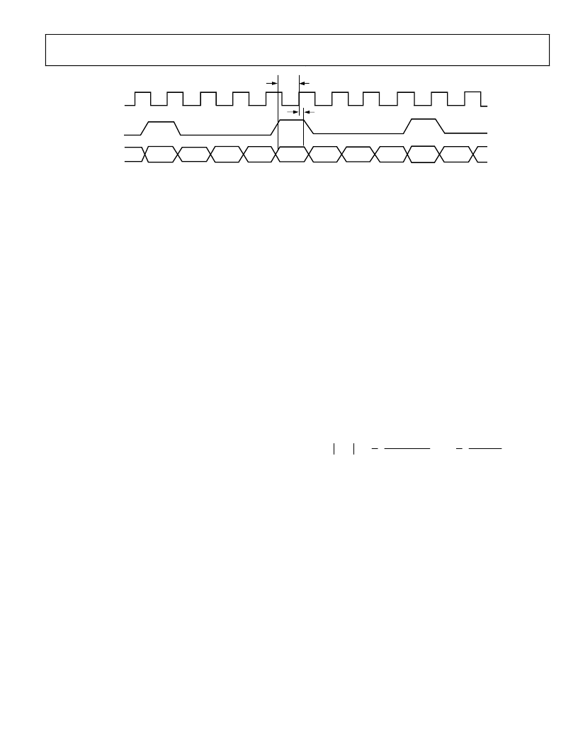
t
SU
t
HU
MCLK
TxSYNC
TxIQ
TxI[11:6]
TxI[5:0]
TxQ[11:6]
TxQ[5:0]
TxI[11:6]
TxI[5:0]
TxQ[11:6]
TxQ[5:0]
TxI[11:6]
TxI[5:0]
0
Figure 24. Tx Timing Diagram
TRANSMIT PATH
The transmit path contains an interpolation filter, a complete
quadrature digital upconverter, an inverse sinc filter, and a 12-bit
current output DAC. The maximum output current of the DAC is
set by an external resistor. The Tx output PGA provides additional
transmit signal level control. The transmit path interpolation
filter provides an upsampling factor of 16 with an output signal
bandwidth as high as 4.35 MHz for <1 dB droop. Carrier
frequencies up to 65 MHz with 26 bits of frequency tuning
resolution can be generated by the direct digital synthesizer
(DDS). The transmit DAC resolution is 12 bits, and it can run at
sampling rates of up to 232 MSPS. Analog output scaling from
0 dB to 7.5 dB in 0.5 dB steps is available to preserve SNR when
reduced output levels are required.
DATA ASSEMBLER
The AD9878 data path operates on two 12-bit words, the I and Q
components, that form a complex symbol. The data assembler
builds the 24-bit complex symbol from four consecutive 6-bit
words read over the TxIQ [5:0] bus. These words are strobed
into the data assembler synchronous to the master clock (MCLK).
A high level on TxSYNC signals the start of a transmit symbol.
The first two 6-bit words of the symbol form the I component;
the second two 6-bit words form the Q component. Symbol
components are assumed to be in twos complement format. The
timing of the interface is fully described in the Transmit Timing
section. The I/Q sample rate f
IQCLK
puts a bandwidth limit on the
maximum transmit spectrum. This is the familiar Nyquist limit
(hereafter referred to as f
NYQ
) and is equal to half f
IQCLK
.
TRANSMIT TIMING
The AD9878 has a master clock and expects 6-bit, multiplexed
TxIQ data upon each rising edge (see Figure 24). Transmit
symbols are framed with the TxSYNC input. TxSYNC high
indicates the start of a transmit symbol. Four consecutive 6-bit
data packages form a symbol (I MSB, I LSB, Q MSB, and Q LSB).
INTERPOLATION FILTER
Once through the data assembler, the IQ data streams are fed
through a 4× FIR low-pass filter and a 4× cascaded integrator
comb (CIC) low-pass filter. The combination of these two filters
results in the sample rate increasing by a factor of 16. In addition
to the sample rate increase, the half-band filters provide the
low-pass filtering characteristics necessary to suppress the spectral
images between the original sampling frequency and the new
(16× higher) sampling frequency.
HALF-BAND FILTERS (HBFs)
HBF 1 and HBF 2 are both interpolating filters, each of which
doubles the sampling rate. Together, HBF 1 and HBF 2 have
26 taps and increase the sampling rate by a factor of 4
(4 × f
IQCLK
or 8 × f
NYQ
).
In relation to phase response, both HBFs are linear phase filters.
As such, virtually no phase distortion is introduced within the pass
band of the filters. This is an important feature, because phase dis-
tortion is generally intolerable in a data transmission system.
CASCADE INTEGRATOR COMB (CIC) FILTER
The CIC filter is configured as a programmable interpolator
and provides a sample rate increase by a factor of 4. The
frequency response of the CIC filter is given by:
( )
( )
4
(
)
(
)
( )
3
3
π
2
π
2
sin
π
4
sin
4
1
1
1
4
1
=
f
e
e
H
f
j
f
j
COMBINED FILTER RESPONSE
The combined frequency response of the HBF and CIC filters
limits the input signal bandwidth that can be propagated through
the AD9878.The usable bandwidth of the filter chain limits the
maximum data rate that can be propagated through the AD9878.
A look at the pass-band detail of the combined filter response
(Figure 25) indicates that to maintain an amplitude error of
1 dB or less, signal bandwidth is restricted to about 60% or less
of f
NYQ
.
Max BW
(1dB droop)
= 0.60 * f
MCLK
/8
Thus, in order to keep the bandwidth of the data in the flat
portion of the filter pass band, the user must oversample the
baseband data by at least a factor of two prior to presenting it to
the AD9878. Note that without oversampling, the Nyquist
bandwidth of the baseband data corresponds to f
NYQ
. As such,
the upper end of the data bandwidth suffers 6 dB or more of
attenuation due to the frequency response of the digital filters.
Furthermore, if the baseband data applied to the AD9878 has
相关PDF资料 |
PDF描述 |
|---|---|
| AD9878BSTZ | Mixed-Signal Front End for Broadband Applications |
| ADAV801 | Audio Codec for Recordable DVD |
| ADAV801ASTZ | Audio Codec for Recordable DVD |
| ADAV801ASTZ-REEL | Audio Codec for Recordable DVD |
| ADC0800PCD | ADC0800 8-Bit A/D Converter |
相关代理商/技术参数 |
参数描述 |
|---|---|
| AD9878BSTRL | 制造商:Analog Devices 功能描述:Mixed Signal Front End 100-Pin LQFP T/R 制造商:Analog Devices 功能描述:MIXED SGNL FRONT END 100LQFP - Tape and Reel |
| AD9878BSTZ | 功能描述:IC FRONT-END MIXED-SGNL 100-LQFP RoHS:是 类别:集成电路 (IC) >> 数据采集 - 模拟前端 (AFE) 系列:- 产品培训模块:Lead (SnPb) Finish for COTS Obsolescence Mitigation Program 标准包装:2,500 系列:- 位数:- 通道数:2 功率(瓦特):- 电压 - 电源,模拟:3 V ~ 3.6 V 电压 - 电源,数字:3 V ~ 3.6 V 封装/外壳:32-VFQFN 裸露焊盘 供应商设备封装:32-QFN(5x5) 包装:带卷 (TR) |
| AD9878-EB | 制造商:Analog Devices 功能描述:EVAL KIT FOR MIXED-SGNL FRONT END FOR BROADBAND APPLICATIONS - Bulk |
| AD9879 | 制造商:AD 制造商全称:Analog Devices 功能描述:Mixed-Signal Front End Set-Top Box, Cable Modem |
| AD9879_05 | 制造商:AD 制造商全称:Analog Devices 功能描述:Mixed-Signal Front End Set-Top Box, Cable Modem |
发布紧急采购,3分钟左右您将得到回复。