- 您现在的位置:买卖IC网 > PDF目录20619 > ADE5569ASTZF62-RL (Analog Devices Inc)IC METER/8052/RTC/LCD DRV 64LQFP PDF资料下载
参数资料
| 型号: | ADE5569ASTZF62-RL |
| 厂商: | Analog Devices Inc |
| 文件页数: | 138/156页 |
| 文件大小: | 0K |
| 描述: | IC METER/8052/RTC/LCD DRV 64LQFP |
| 标准包装: | 1,500 |
| 输入阻抗: | * |
| 测量误差: | * |
| 电压 - 高输入/输出: | * |
| 电压 - 低输入/输出: | * |
| 电流 - 电源: | * |
| 电源电压: | * |
| 测量仪表类型: | * |
| 工作温度: | * |
| 安装类型: | 表面贴装 |
| 封装/外壳: | 64-LQFP |
| 供应商设备封装: | 64-LQFP(10x10) |
| 包装: | 带卷 (TR) |
第1页第2页第3页第4页第5页第6页第7页第8页第9页第10页第11页第12页第13页第14页第15页第16页第17页第18页第19页第20页第21页第22页第23页第24页第25页第26页第27页第28页第29页第30页第31页第32页第33页第34页第35页第36页第37页第38页第39页第40页第41页第42页第43页第44页第45页第46页第47页第48页第49页第50页第51页第52页第53页第54页第55页第56页第57页第58页第59页第60页第61页第62页第63页第64页第65页第66页第67页第68页第69页第70页第71页第72页第73页第74页第75页第76页第77页第78页第79页第80页第81页第82页第83页第84页第85页第86页第87页第88页第89页第90页第91页第92页第93页第94页第95页第96页第97页第98页第99页第100页第101页第102页第103页第104页第105页第106页第107页第108页第109页第110页第111页第112页第113页第114页第115页第116页第117页第118页第119页第120页第121页第122页第123页第124页第125页第126页第127页第128页第129页第130页第131页第132页第133页第134页第135页第136页第137页当前第138页第139页第140页第141页第142页第143页第144页第145页第146页第147页第148页第149页第150页第151页第152页第153页第154页第155页第156页
�� �
�
�ADE5166/ADE5169/ADE5566/ADE5569�
�UART2� OPERATION� MODES�
�The� UART2� has� two� operation� modes� in� which� each� data� byte�
�(LSB� first)� is� preceded� by� a� start� bit� (0),� followed� by� a� stop� bit�
�(1).� Therefore,� each� frame� consists� of� 10� bits� transmitted� on� the�
�TxD2� pin� or� received� on� the� RxD2� pin.�
�The� baud� rate� is� set� by� a� dedicated� timer� for� baud� rate� genera-�
�tion,� the� UART2� timer,� which� has� a� fractional� divisor� to� precisely�
�generate� any� baud� rate.�
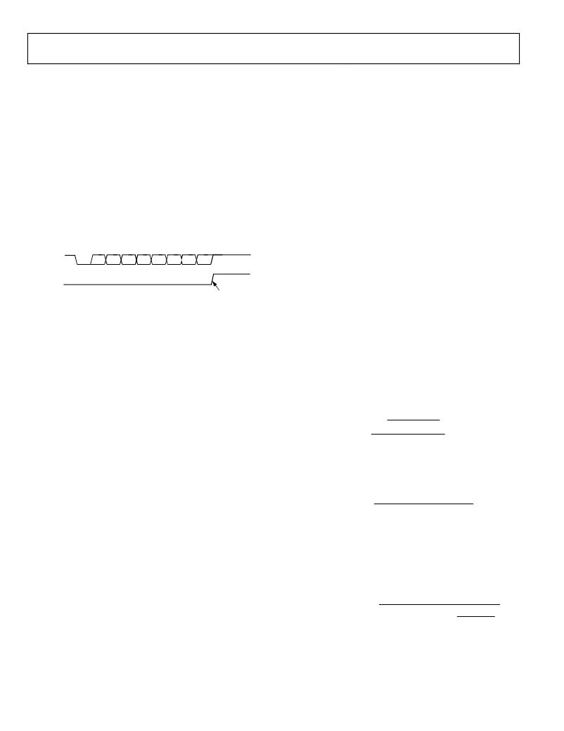
�Transmission� is� initiated� by� a� write� to� the� Serial� Port� 2� buffer� SFR�
�(SBUF2,� Address� 0xEB).� Next,� a� stop� bit� (1)� is� loaded� into� the�
�ninth� bit� position� of� the� serial� port� shift� register.� The� data� is� output�
�bit� by� bit� until� the� stop� bit� appears� on� the� TxD2� pin,� and� the�
�Serial� Port� 2� transmit� interrupt� flag,� TI2� (SCON2[1])� is� auto-�
�matically� set,� as� shown� in� Figure� 111.�
�Data� Sheet�
�9-Bit� UART2� with� Variable� Baud� Rate�
�Setting� EN-T8� (SCON2[6])� selects� the� 9-bit� mode.� In� this� mode,�
�the� UART2� serial� port� operates� in� 9-bit� mode� with� a� variable� baud�
�rate.� The� baud� rate� is� set� by� a� dedicated� timer� for� baud� rate� gen-�
�eration,� the� UART2� timer,� which� has� a� fractional� divisor� to�
�precisely� generate� any� baud� rate� (see� the� UART2� Timer� Generated�
�Baud� Rates� section).� The� operation� of� the� 9-bit� UART2� is� the�
�same� as� for� the� 9-bit� mode� of� the� UART.�
�In� both� modes,� transmission� is� initiated� by� any� instruction� that�
�uses� SBUF2� as� a� destination� register.� Reception� is� initiated� in�
�8-bit� mode� when� RI2� =� 0� and� REN2� =� 1� in� the� SCON2� SFR.� Recep-�
�tion� is� initiated� in� the� 9-bit� mode� by� the� incoming� start� bit� if�
�REN2� =� 1.�
�UART2� BAUD� RATE� GENERATION�
�TxD2�
�START�
�BIT�
�D0�
�D1�
�D2�
�D3�
�D4�
�D5�
�D6�
�D7�
�STOP� BIT�
�The� baud� rate� is� determined� by� the� overflow� rate� of� the� dedicated�
�baud� rate� generator,� the� UART2� timer,� which� has� an� integer� and�
�TI2�
�(SCON2[1])�
�SET� INTERRUPT�
�(FOR� EXAMPLE,�
�READY� FOR� MORE� DATA)�
�Figure� 111.� 8-Bit� Variable� Baud� Rate�
�Reception� is� initiated� when� a� 1-to-0� transition� is� detected� on� the�
�RxD2� pin.� Assuming� that� a� valid� start� bit� is� detected,� character�
�reception� continues.� The� eight� data� bits� are� clocked� into� the�
�serial� port� shift� register.�
�All� of� the� following� conditions� must� be� met� at� the� time� the� final�
�shift� pulse� is� generated� to� receive� a� character:�
�fractional� divisor.�
�UART2� Timer� Generated� Baud� Rates�
�The� enhanced� Serial� Baud� Rate� Control� 2� SFR� (SBAUD2,�
�Address� 0xEE)� is� used� to� control� the� UART2� timer.� SBAUD2� is�
�the� baud� rate� control� SFR;� it� sets� up� the� integer� divider� (DIV2,�
�SBAUD2[2:0])� and� the� extended� divider� (SBTH2,� SBAUD2[4:3])�
�for� the� UART2� timer.�
�The� desired� value� to� write� to� DIV2� and� to� SBTH2� can� be� cal-�
�culated� using� the� following� formula,� where� f� core� is� defined� in� the�
�POWCON� SFR.� Note� that� the� DIV2� value� must� be� rounded�
�down� to� the� nearest� integer.�
�f� core�
�log� ?�
�?�
�?�
�If� the� extended� UART� is� disabled� (EXTEN� =� 0,� CFG[6]),�
�RI2� (SCON2[0])� must� be� 0� to� receive� a� character.� This� ensures�
�that� the� data� in� the� SBUF2� SFR� is� not� overwritten� if� the� last�
�received� character� has� not� been� read.�
�DIV2� +� SBTH2� =�
�?� ?�
�?� ?�
�?� 16� � Baud� Rate� ?�
�log� (� 2� )�
�f� core�
�SBAUDF2� =� 64� � ?�
�?� 1� ?�
�?� 16� � 2�
�� Baud� Rate�
�?�
�?�
�f� core�
�SBAUDF� 2� ?�
�16� � 2� DIV� 2� +� SBTH� 2� � ?� ?� 1� +�
�?�
�?�
�64�
�?� If� frame� error� checking� is� enabled� by� setting� FE2� (SCON2[4]),�
�the� received� stop� bit� must� be� set� to� receive� a� character.� This�
�ensures� that� every� character� received� comes� from� a� valid�
�frame,� with� both� a� start� bit� and� a� stop� bit.�
�If� any� of� these� conditions� is� not� met,� the� received� frame� is� irre-�
�trievably� lost,� and� the� Serial� Port� 2� receive� interrupt� flag,� RI2�
�(SCON2[0]),� is� not� set.�
�If� the� received� frame� meets� the� preceding� conditions,� the� fol-�
�lowing� events� occur:�
�?� The� eight� bits� in� the� receive� shift� register� are� latched� into�
�SBUF2.�
�?� The� Serial� Port� 2� receiver� interrupt� flag� (RI2)� is� set.�
�Transmission� is� initiated� by� any� instruction� that� uses� SBUF2� as�
�a� destination� register.� Reception� is� initiated� by� the� incoming� start�
�bit� if� REN2� =� 1� in� the� SCON2� SFR,� Address0xE1[2].�
�SBAUDF2� is� the� fractional� divider� ratio� required� to� achieve� the�
�required� baud� rate.� The� appropriate� value� for� SBAUDF2� can� be�
�calculated� with� the� following� formula:�
�?� ?�
�DIV� 2� +� SBTH� 2� ?�
�Note� that� SBAUDF2� can� take� only� two� values,� 0x2B� or� 0x07,� by�
�clearing� or� by� setting� the� SBF2� bit� (SBAUD2[5]),� respectively.�
�These� values� were� chosen� to� provide� an� accurate� baud� rate� for�
�300,� 2400,� 4800,� 9600,� 19,200,� 38,400,� 57,600,� and� 115,200� bps.�
�When� DIV2� and� SBAUDF2� are� calculated,� the� actual� baud� rate�
�can� be� calculated,� using� the� following� formula:�
�Actual� Baud� Rate� =�
�?�
�Rev.� D� |� Page� 138� of� 156�
�相关PDF资料 |
PDF描述 |
|---|---|
| HMC49DRTF-S13 | CONN EDGECARD 98POS .100 EXTEND |
| VLF4014AT-100MR90 | INDUCTOR POWER 10UH .9A SMD |
| CS5464-ISZ | IC ENERGY METERING 1PHASE 28SSOP |
| ADE7752AARZ | IC ENERGY METERING 3PHASE 24SOIC |
| ADE7816ACPZ-RL | IC ENERGY METERING 40LFCSP |
相关代理商/技术参数 |
参数描述 |
|---|---|
| ADE-6 | 制造商:MINI 制造商全称:Mini-Circuits 功能描述:Surface Mount Frequency Mixer |
| ADE7116ASTZF16 | 功能描述:IC ENERGY METER 64-LQFP RoHS:是 类别:集成电路 (IC) >> PMIC - 能量测量 系列:- 产品培训模块:Lead (SnPb) Finish for COTS Obsolescence Mitigation Program 标准包装:2,500 系列:* |
| ADE7116ASTZF16-RL | 功能描述:IC ENERGY METER 64-LQFP RoHS:是 类别:集成电路 (IC) >> PMIC - 能量测量 系列:- 产品培训模块:Lead (SnPb) Finish for COTS Obsolescence Mitigation Program 标准包装:2,500 系列:* |
| ADE7116ASTZF8 | 功能描述:IC ENERGY METER 64-LQFP RoHS:是 类别:集成电路 (IC) >> PMIC - 能量测量 系列:- 产品培训模块:Lead (SnPb) Finish for COTS Obsolescence Mitigation Program 标准包装:2,500 系列:* |
| ADE7116ASTZF8-RL | 功能描述:IC ENERGY METER 64-LQFP RoHS:是 类别:集成电路 (IC) >> PMIC - 能量测量 系列:- 产品培训模块:Lead (SnPb) Finish for COTS Obsolescence Mitigation Program 标准包装:2,500 系列:* |
发布紧急采购,3分钟左右您将得到回复。