- 您现在的位置:买卖IC网 > PDF目录15354 > ADP1878ACPZ-0.6-R7 (Analog Devices Inc)IC REG CTRLR BUCK PWM CM 14LFCSP PDF资料下载
参数资料
| 型号: | ADP1878ACPZ-0.6-R7 |
| 厂商: | Analog Devices Inc |
| 文件页数: | 24/40页 |
| 文件大小: | 0K |
| 描述: | IC REG CTRLR BUCK PWM CM 14LFCSP |
| 标准包装: | 1,500 |
| PWM 型: | 电流模式 |
| 输出数: | 1 |
| 频率 - 最大: | 600kHz |
| 占空比: | 65% |
| 电源电压: | 2.95 V ~ 20 V |
| 降压: | 是 |
| 升压: | 无 |
| 回扫: | 无 |
| 反相: | 无 |
| 倍增器: | 无 |
| 除法器: | 无 |
| Cuk: | 无 |
| 隔离: | 无 |
| 工作温度: | -40°C ~ 125°C |
| 封装/外壳: | 14-WFDFN 裸露焊盘,CSP |
| 包装: | 带卷 (TR) |
第1页第2页第3页第4页第5页第6页第7页第8页第9页第10页第11页第12页第13页第14页第15页第16页第17页第18页第19页第20页第21页第22页第23页当前第24页第25页第26页第27页第28页第29页第30页第31页第32页第33页第34页第35页第36页第37页第38页第39页第40页
�� ��
��
��(� ??� ??????� ?� 0.6� V� )�
�??� ??� =� ??� ??� �
�??� ????????�
�???� ??� =� ??� ??� � ??� ????????�
�≈�
�(� ??� ????� ?� ??� ??????� )� ??� ??????�
�??� =�
��
�ADP1878/ADP1879�
�APPLICATIONS� INFORMATION�
�FEEDBACK� RESISTOR� DIVIDER�
�The� required� resistor� divider� network� can� be� determined� for� a�
�given� V� OUT� value� because� the� internal� band� gap� reference� (V� REF� )�
�is� fixed� at� 0.6� V.� Selecting� values� for� R� T� and� R� B� determine� the�
�minimum� output� load� current� of� the� converter.� Therefore,� for� a�
�given� value� of� R� B� ,� the� R� T� value� can� be� determined� through� the�
�following� expression:�
�0.6� V�
�INDUCTOR� SELECTION�
�The� inductor� value� is� inversely� proportional� to� the� inductor�
�ripple� current.� The� peak-to-peak� ripple� current� is� given� by�
�where� K� I� is� typically� 0.33.� 3�
�The� equation� for� the� inductor� value� is� given� by�
�where:� ???� ??� � ??� ????� ??� ????�
�V� IN� is� the� high� voltage� input.�
�V� OUT� is� the� desired� output� voltage.�
�f� SW� is� the� controller� switching� frequency� (300� kHz,� 600� kHz,� and�
�1.0� MHz).�
�When� selecting� the� inductor,� choose� an� inductor� saturation�
�rating� that� is� above� the� peak� current� level,� and� then� calculate�
�the� inductor� current� ripple� (see� the� Valley� Current-Limit�
��Data� Sheet�
�Table� 8.� Recommended� Inductors�
�L� DCR� I� SAT� Dimensions� Model�
�(μH)� (mΩ)� (A)� (mm)� Manufacturer� Number�
�0.12� 0.33� 55� 10.2� ×� 7� Würth� Elek.� 744303012�
�0.22� 0.33� 30� 10.2� ×� 7� Würth� Elek.� 744303022�
�0.47� 0.8� 50� 14.2� ×� 12.8� Würth� Elek.� 744355147�
�0.72� 1.65� 35� 10.5� ×� 10.2� Würth� Elek.� 744325072�
�0.9� 1.6� 32� 14� ×� 12.8� Würth� Elek.� 744318120�
�1.2� 1.8� 25� 10.5� ×� 10.2� Würth� Elek.� 744325120�
�1.0� 3.8� 16� 10.2� ×� 10.2� Würth� Elek.� 7443552100�
�1.4� 3.2� 24� 14� ×� 12.8� Würth� Elek.� 744318180�
�2.0� 2.6� 23� 10.2� ×� 10.2� Würth� Elek.� 7443551200�
�0.8� 27.5� Sumida� CEP125U-0R8�
�OUTPUT� RIPPLE� VOLTAGE� (ΔV� RR� )�
�The� output� ripple� voltage� is� the� ac� component� of� the� dc� output�
�voltage� during� steady� state.� For� a� ripple� error� of� 1.0%,� the� output�
�capacitor� value� needed� to� achieve� this� tolerance� can� be� determined�
�using� the� following� equation.� (Note� that� an� accuracy� of� 1.0%� is�
�possible� during� steady� state� conditions� only,� not� during� load�
�transients.)�
�ΔV� RR� =� (0.01)� ×� V� OUT�
�OUTPUT� CAPACITOR� SELECTION�
�The� primary� objective� of� the� output� capacitor� is� to� facilitate� the�
�reduction� of� the� output� voltage� ripple;� however,� the� output� capacitor�
�also� assists� in� the� output� voltage� recovery� during� load� transient�
�events.� For� a� given� load� current� step,� the� output� voltage� ripple�
�generated� during� this� step� event� is� inversely� proportional� to� the�
�value� chosen� for� the� output� capacitor.� The� speed� at� which� the�
�output� voltage� settles� during� this� recovery� period� depends� on�
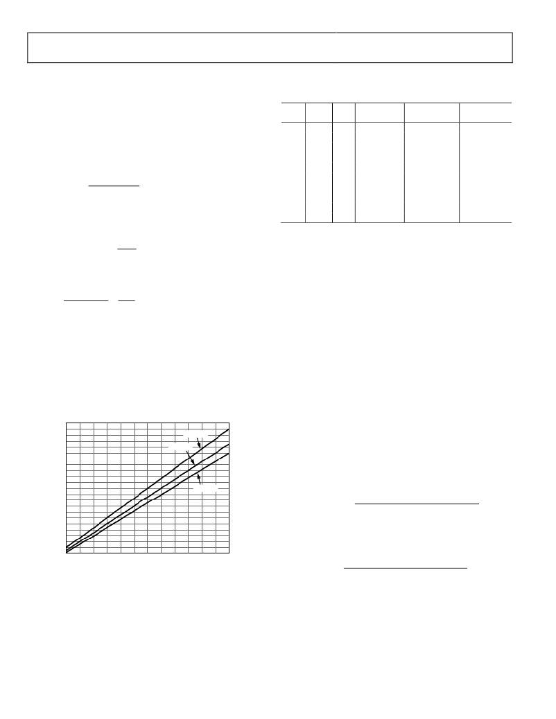
�52�
�50�
�48�
�46�
�44�
�42�
�40�
�38�
�ΔI = 50%�
�ΔI = 40%�
�where� the� crossover� frequency� (loop� bandwidth)� is� set.� This�
�crossover� frequency� is� determined� by� the� output� capacitor,� the�
�equivalent� series� resistance� (ESR)� of� the� capacitor,� and� the�
�compensation� network.�
�1�
�??� ??????� =� ???� ??� � ?�
�?�
�???� ????????�
�??� ??????� =� 2� �
�36�
�34�
�32�
�30� ΔI = 33%�
�28�
�26�
�24�
�22�
�20�
�18�
�16�
�14�
�12�
�10�
�8�
�6� 8� 10� 12� 14� 16� 18� 20� 22� 24� 26� 28� 30�
�VALLEY� CURRENT� LIMIT� (A)�
�Figure� 81.� Peak� Inductor� Current� vs.� Valley� Current� Limit� for� 33%,� 40%,� and�
�50%� of� Inductor� Ripple� Current�
�To� calculate� the� small� signal� voltage� ripple� (output� ripple� voltage)� at�
�the� steady� state� operating� point,� use� the� following� equation:�
�8� � ??� ????� � [� ???� ????????????� ?� (� of� � ??????� )]�
�where� ESR� is� the� equivalent� series� resistance� ???� ??� the� output�
�capacitors.�
�To� calculate� the� output� load� step,� use� the� following� equation:�
�??� ????� � ????� that� V� (� ???� is� � ??????� )�
�where� Δ� V� DROOP� is� the� amount� ??????????� ?� OUT� ????????� allowed� to� ?� deviate� for�
�a� given� positive� load� current� step� (Δ� I� LOAD� ).�
�Rev.� B� |� Page� 24� of� 40�
�相关PDF资料 |
PDF描述 |
|---|---|
| VE-2WN-EY-F1 | CONVERTER MOD DC/DC 18.5V 50W |
| VI-B1F-EV-F1 | CONVERTER MOD DC/DC 72V 150W |
| ACC08DREN-S734 | CONN EDGECARD 16POS .100 EYELET |
| UCA2C680MHD6 | CAP ALUM 68UF 160V 20% RADIAL |
| VE-2WM-EY-F4 | CONVERTER MOD DC/DC 10V 50W |
相关代理商/技术参数 |
参数描述 |
|---|---|
| ADP1878ACPZ-1.0-R7 | 功能描述:IC REG CTRLR BUCK PWM CM 14LFCSP RoHS:是 类别:集成电路 (IC) >> PMIC - 稳压器 - DC DC 切换控制器 系列:- 标准包装:2,500 系列:- PWM 型:电流模式 输出数:1 频率 - 最大:500kHz 占空比:96% 电源电压:4 V ~ 36 V 降压:无 升压:是 回扫:无 反相:无 倍增器:无 除法器:无 Cuk:无 隔离:无 工作温度:-40°C ~ 125°C 封装/外壳:24-WQFN 裸露焊盘 包装:带卷 (TR) |
| ADP1879-0.3-EVALZ | 功能描述:BOARD EVAL FOR ADP1879-0.3 RoHS:是 类别:编程器,开发系统 >> 评估板 - DC/DC 与 AC/DC(离线)SMPS 系列:* 标准包装:1 系列:- 主要目的:DC/DC,步降 输出及类型:1,非隔离 功率 - 输出:- 输出电压:3.3V 电流 - 输出:3A 输入电压:4.5 V ~ 28 V 稳压器拓扑结构:降压 频率 - 开关:250kHz 板类型:完全填充 已供物品:板 已用 IC / 零件:L7981 其它名称:497-12113STEVAL-ISA094V1-ND |
| ADP1879-0.6-EVALZ | 功能描述:BOARD EVAL FOR ADP1879-0.6 RoHS:是 类别:编程器,开发系统 >> 评估板 - DC/DC 与 AC/DC(离线)SMPS 系列:* 标准包装:1 系列:- 主要目的:DC/DC,步降 输出及类型:1,非隔离 功率 - 输出:- 输出电压:3.3V 电流 - 输出:3A 输入电压:4.5 V ~ 28 V 稳压器拓扑结构:降压 频率 - 开关:250kHz 板类型:完全填充 已供物品:板 已用 IC / 零件:L7981 其它名称:497-12113STEVAL-ISA094V1-ND |
| ADP1879-1.0-EVALZ | 功能描述:BOARD EVAL FOR ADP1879-1.0 RoHS:是 类别:编程器,开发系统 >> 评估板 - DC/DC 与 AC/DC(离线)SMPS 系列:* 标准包装:1 系列:- 主要目的:DC/DC,步降 输出及类型:1,非隔离 功率 - 输出:- 输出电压:3.3V 电流 - 输出:3A 输入电压:4.5 V ~ 28 V 稳压器拓扑结构:降压 频率 - 开关:250kHz 板类型:完全填充 已供物品:板 已用 IC / 零件:L7981 其它名称:497-12113STEVAL-ISA094V1-ND |
| ADP1879ACPZ-0.3-R7 | 功能描述:IC REG CTRLR BUCK PWM CM 14LFCSP RoHS:是 类别:集成电路 (IC) >> PMIC - 稳压器 - DC DC 切换控制器 系列:- 特色产品:LM3753/54 Scalable 2-Phase Synchronous Buck Controllers 标准包装:1 系列:PowerWise® PWM 型:电压模式 输出数:1 频率 - 最大:1MHz 占空比:81% 电源电压:4.5 V ~ 18 V 降压:是 升压:无 回扫:无 反相:无 倍增器:无 除法器:无 Cuk:无 隔离:无 工作温度:-5°C ~ 125°C 封装/外壳:32-WFQFN 裸露焊盘 包装:Digi-Reel® 产品目录页面:1303 (CN2011-ZH PDF) 其它名称:LM3754SQDKR |
发布紧急采购,3分钟左右您将得到回复。