- 您现在的位置:买卖IC网 > PDF目录17274 > AS5040 DB V2 (ams)BOARD DEMO AS5040 PDF资料下载
参数资料
| 型号: | AS5040 DB V2 |
| 厂商: | ams |
| 文件页数: | 17/34页 |
| 文件大小: | 0K |
| 描述: | BOARD DEMO AS5040 |
| 标准包装: | 1 |
| 传感器类型: | 磁性,旋转位置 |
| 传感范围: | 360° |
| 接口: | USB |
| 电源电压: | 5V USB 或 9V |
| 嵌入式: | 是,MCU,8 位 |
| 已供物品: | 板,线缆 |
| 已用 IC / 零件: | AS5040 |
第1页第2页第3页第4页第5页第6页第7页第8页第9页第10页第11页第12页第13页第14页第15页第16页当前第17页第18页第19页第20页第21页第22页第23页第24页第25页第26页第27页第28页第29页第30页第31页第32页第33页第34页
�� �
�
�AS5040�
�Data� Sheet�
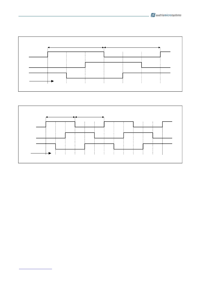
�Figure� 12:� U,� V� and� V-signals� for� BLDC� Motor� Commutation� (Div1=0,� Div0=0)�
�Commutation� -� Mode� 3.0�
�Width:� 512� Steps�
�U�
�V�
�W�
�CW� Direction�
�(One-pole-pair)�
�Width:� 512� Steps�
�Position:�
�Angle:�
�0�
�0.0�
�171�
�60.12�
�341�
�119.88�
�512�
�180.0�
�683�
�240.12�
�853�
�299.88�
�0�
�360.0�
�Figure� 13:� U,� V� and� W-signals� for� 2-pole� BLDC� Motor� Commutation� (Div1=1;� Div0=0)�
�Commutation� -� Mode� 3.2�
�(Two-pole-pairs)�
�U�
�V�
�W�
�CW� Direction�
�Width:� 256� Steps�
�Width:� 256� Steps�
�Position:�
�Angle:�
�0�
�0.0�
�85�
�29.88�
�171�
�60.12�
�256�
�90.0�
�341�
�119.88�
�427�
�150.12�
�512�
�180.0�
�597�
�209.88�
�683�
�240.12�
�768�
�270.00�
�853�
�299.88�
�939�
�330.12�
�0�
�360.0�
�12� Programming� the� AS5040�
�After� power-on,� programming� the� AS5040� is� enabled� with� the� rising� edge� of� CSn� with� Prog� =� high� and� CLK� =� low.� 16�
�bit� configuration� data� must� be� serially� shifted� into� the� OTP� register� via� the� Prog-pin.� The� first� “CCW”� bit� is� followed� by�
�the� zero� position� data� (MSB� first)� and� the� incremental� mode� setting� as� shown� in� Table� 6.� Data� must� be� valid� at� the�
�rising� edge� of� CLK� (see� Figure� 14).�
�After� writing� data� into� the� OTP� register� it� can� be� permanently� programmed� by� rising� the� Prog� pin� to� the� programming�
�voltage� V� PROG� .� 16� CLK� pulses� (t� PROG� )� must� be� applied� to� program� the� fuses� (Figure� 15).� To� exit� the� programming�
�mode,� the� chip� must� be� reset� by� a� power-on-reset.� The� programmed� data� is� available� after� the� next� power-up.�
�Note:� During� the� programming� process,� the� transitions� in� the� programming� current� may� cause� high� voltage� spikes�
�generated� by� the� inductance� of� the� connection� cable.� To� avoid� these� spikes� and� possible� damage� to� the� IC,� the�
�connection� wires,� especially� the� signals� Prog� and� VSS� must� be� kept� as� short� as� possible.� The� maximum� wire� length�
�between� the� V� PROG� switching� transistor� and� pin� Prog� (see� Figure� 16)� should� not� exceed� 50mm� (2� inches).� To�
�suppress� eventual� voltage� spikes,� a� 10nF� ceramic� capacitor� should� be� connected� close� to� pins� Prog� and� VSS.� This�
�capacitor� is� only� required� for� programming,� it� is� not� required� for� normal� operation.�
�The� clock� timing� t� clk� must� be� selected� at� a� proper� rate� to� ensure� that� the� signal� Prog� is� stable� at� the� rising� edge� of� CLK�
�(see� Figure� 14).� Additionally,� the� programming� supply� voltage� should� be� buffered� with� a� 10μF� capacitor� mounted�
�close� to� the� switching� transistor.� This� capacitor� aids� in� providing� peak� currents� during� programming.�
�The� specified� programming� voltage� at� pin� Prog� is� 7.3� –� 7.5V� (see� section� 0).� To� compensate� for� the� voltage� drop�
�across� the� V� PROG� switching� transistor,� the� applied� programming� voltage� may� be� set� slightly� higher� (7.5� -� 8.0V,� see�
�Figure� 16).�
�www.austriamicrosystems.com�
�Revision� 2.10�
�16� -� 33�
�相关PDF资料 |
PDF描述 |
|---|---|
| EEC22DREI | CONN EDGECARD 44POS .100 EYELET |
| MAX15035EVKIT+ | EVALUATION KIT FOR MAX15035 |
| 592D336X0010D2W15H | CAP TANT 33UF 10V 20% 2917 |
| L-14CR22JV4T | CER INDUCTOR 220NH 0603 |
| ECC20DCSN | CONN EDGECARD 40POS DIP .100 SLD |
相关代理商/技术参数 |
参数描述 |
|---|---|
| AS5040-PB | 功能描述:磁传感器开发工具 AS5040 Progamming Board RoHS:否 制造商:Maxim Integrated 工具用于评估: 接口类型: 工作电压: |
| AS5040-SS_EK_AB | 功能描述:AS5040 - Magnetic, Rotary Position Sensor Evaluation Board 制造商:ams 系列:- 零件状态:有效 传感器类型:磁性,旋转位置 感应范围:360° 接口:串行 灵敏度:- 电压 - 电源:9V 嵌入式:否 所含物品:板 使用的 IC/零件:AS5040 标准包装:1 |
| AS5040-SS_EK_DB | 功能描述:AS5040 - Magnetic, Rotary Position Sensor Evaluation Board 制造商:ams 系列:- 零件状态:有效 传感器类型:磁性,旋转位置 感应范围:360° 接口:USB 灵敏度:- 电压 - 电源:5V USB 或 9V 嵌入式:是,MCU,8 位 所含物品:板,线缆 使用的 IC/零件:AS5040 标准包装:1 |
| AS5040-SS_EK_PB | 功能描述:AS5000 Programmer, AS5040 - ZIF Socket 制造商:ams 系列:- 零件状态:有效 模块/板类型:ZIF 插口 配套使用产品/相关产品:AS5000 编程器,AS5040 标准包装:1 |
| AS-5041 | 制造商:Bud Industries Inc 功能描述: |
发布紧急采购,3分钟左右您将得到回复。