参数资料
| 型号: | AS8510-ASST |
| 厂商: | ams |
| 文件页数: | 16/47页 |
| 文件大小: | 0K |
| 描述: | IC BATTERY MANAGEMENT 20-SSOP |
| 产品培训模块: | AS8510 Data Acquisition IC |
| 标准包装: | 2,000 |
| 类型: | 电池管理 |
| 输入类型: | 模拟,数字 |
| 输出类型: | 模拟,数字 |
| 接口: | SPI 串行 |
| 电流 - 电源: | 5mA |
| 安装类型: | 表面贴装 |
| 封装/外壳: | 20-SSOP(0.209",5.30mm 宽) |
| 供应商设备封装: | 20-SSOP |
| 包装: | 带卷 (TR) |
第1页第2页第3页第4页第5页第6页第7页第8页第9页第10页第11页第12页第13页第14页第15页当前第16页第17页第18页第19页第20页第21页第22页第23页第24页第25页第26页第27页第28页第29页第30页第31页第32页第33页第34页第35页第36页第37页第38页第39页第40页第41页第42页第43页第44页第45页第46页第47页
Revision 3.5
22 - 46
AS8510
Datasheet - Detailed Descr i p ti on
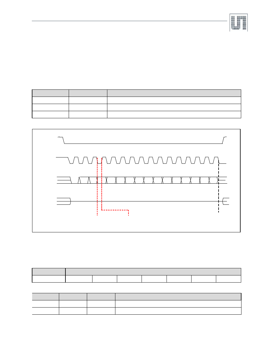
7.8 4-Wire Serial Port Interface
The SPI interface is used as interface between the AS8510 and an external micro-controller to configure the device and access the status
information. The micro-controller begins communication with the SPI which is configured as a slave. The SPI protocol is simple and the length of
each frame is an integer multiple of bytes except when a transmission is started. Each frame has 1 command bit, 7 address/configuration bits,
and one or more data bytes. The edge of CS and the level of SCLK during the start of a SPI transaction, determine the edge on which the data is
transferred from the SPI and the edge on which the data is sampled by the slave. Table 29 describes the setting of the transfer and sampling
edges of SCLK. Figure 9 shows the falling edge and rising edge for data transfer and data sampling respectively, when SCLK is HIGH on the
falling edge of CS.
Figure 9. Protocol for Serial Data Write with Length = 1
7.8.1 SPI Frame
A frame is formed by a first byte for command and address/configuration and a following bit stream that can be formed by an integer number of
bytes. Command is coded on the 1 first bit, while address is given on LSB 7 bits (see Table 30).
If the command is read or write, one or more bytes follow. When the micro-controller sends more bytes (keeping CS LOW and SCLK toggling),
the SPI interface increments the address of the previous data byte and writes/reads data to/from consecutive addresses.
Table 29. CS and SCLK
CS
SCLK
Description
FALL
LOW
Serial data transferred on rising edge of SPI clock. Sampled at falling edge of SPI clock.
FALL
HIGH
Serial data transferred on falling edge of SPI clock. Sampled at rising edge of SPI clock.
ANY
Serial data transfer edge is unchanged.
Table 30. Command Bits
Command Bits
Register Address or Transmission Configuration
C0
A6
A5
A4
A3
A2
A1
A0
Table 31. Command Bits
C0
Command
<A6:A0>
Description
0
WRITE
ADDRESS
Writes data byte on the given starting address.
1
READ
ADDRESS
Read data byte from the given starting address.
CS
SCLK
SDI
SDO
0
A6
A5
A4
A0
A1
A2
A3
D0
D1
D2
D3
D4
D5
D7
D6
Transfer edge
Sampling edge
Data D7 – D0 is moved
to Address A4..A0 here
相关PDF资料 |
PDF描述 |
|---|---|
| AS8530-ASOT-002-500 | IC TXRX LIN COMPANION 8-SOIC |
| AS8530A-ASOT-500 | IC SYSTEM BASIS CHIP 8-SOIC |
| AT17F080-30TQI | IC FLASH CONFIG 8M 44TQFP |
| AT17F080A-30QI | IC FLASH CONFIG 8M 32TQFP |
| AT17F16-30TQI | IC FLASH CONFIG 16M 44TQFP |
相关代理商/技术参数 |
参数描述 |
|---|---|
| AS8510-ASST-500 | 功能描述:IC BATTERY MANAGEMENT 20-SSOP RoHS:是 类别:集成电路 (IC) >> 接口 - 传感器和探测器接口 系列:- 其它有关文件:Automotive Product Guide 产品培训模块:Lead (SnPb) Finish for COTS Obsolescence Mitigation Program 标准包装:74 系列:- 类型:触控式传感器 输入类型:数字 输出类型:数字 接口:JTAG,串行 电流 - 电源:100µA 安装类型:表面贴装 封装/外壳:20-TSSOP(0.173",4.40mm 宽) 供应商设备封装:20-TSSOP 包装:管件 |
| AS8510-COPPER-SHUNT | 功能描述:DEMO BOARD FOR AS8510 制造商:ams 系列:- 零件状态:在售 主要用途:接口,数据捕捉 嵌入式:- 使用的 IC/零件:AS8510 主要属性:- 辅助属性:图形用户界面 所含物品:板 标准包装:1 |
| AS8510-DB | 制造商:ams 功能描述:AS8510 Demo Board |
| AS8515-ZMFM | 制造商:ams 功能描述:IC BATTERY MANAGEMENT 制造商:ams 功能描述:Data Acquisition System w/ Power Management and LIN Transceiver - MLF-32 制造商:ams 功能描述:T&R / MLF 32 (5x5) |
| AS8515-ZMFP | 制造商:ams 功能描述:IC INTERFACE TRANSCEIVER 制造商:ams 功能描述:T&R / MLF 32 (5x5) |
发布紧急采购,3分钟左右您将得到回复。