参数资料
| 型号: | AS8510-ASST |
| 厂商: | ams |
| 文件页数: | 33/47页 |
| 文件大小: | 0K |
| 描述: | IC BATTERY MANAGEMENT 20-SSOP |
| 产品培训模块: | AS8510 Data Acquisition IC |
| 标准包装: | 2,000 |
| 类型: | 电池管理 |
| 输入类型: | 模拟,数字 |
| 输出类型: | 模拟,数字 |
| 接口: | SPI 串行 |
| 电流 - 电源: | 5mA |
| 安装类型: | 表面贴装 |
| 封装/外壳: | 20-SSOP(0.209",5.30mm 宽) |
| 供应商设备封装: | 20-SSOP |
| 包装: | 带卷 (TR) |
第1页第2页第3页第4页第5页第6页第7页第8页第9页第10页第11页第12页第13页第14页第15页第16页第17页第18页第19页第20页第21页第22页第23页第24页第25页第26页第27页第28页第29页第30页第31页第32页当前第33页第34页第35页第36页第37页第38页第39页第40页第41页第42页第43页第44页第45页第46页第47页
Revision 3.5
38 - 46
AS8510
Datasheet - Detailed Descr i p ti on
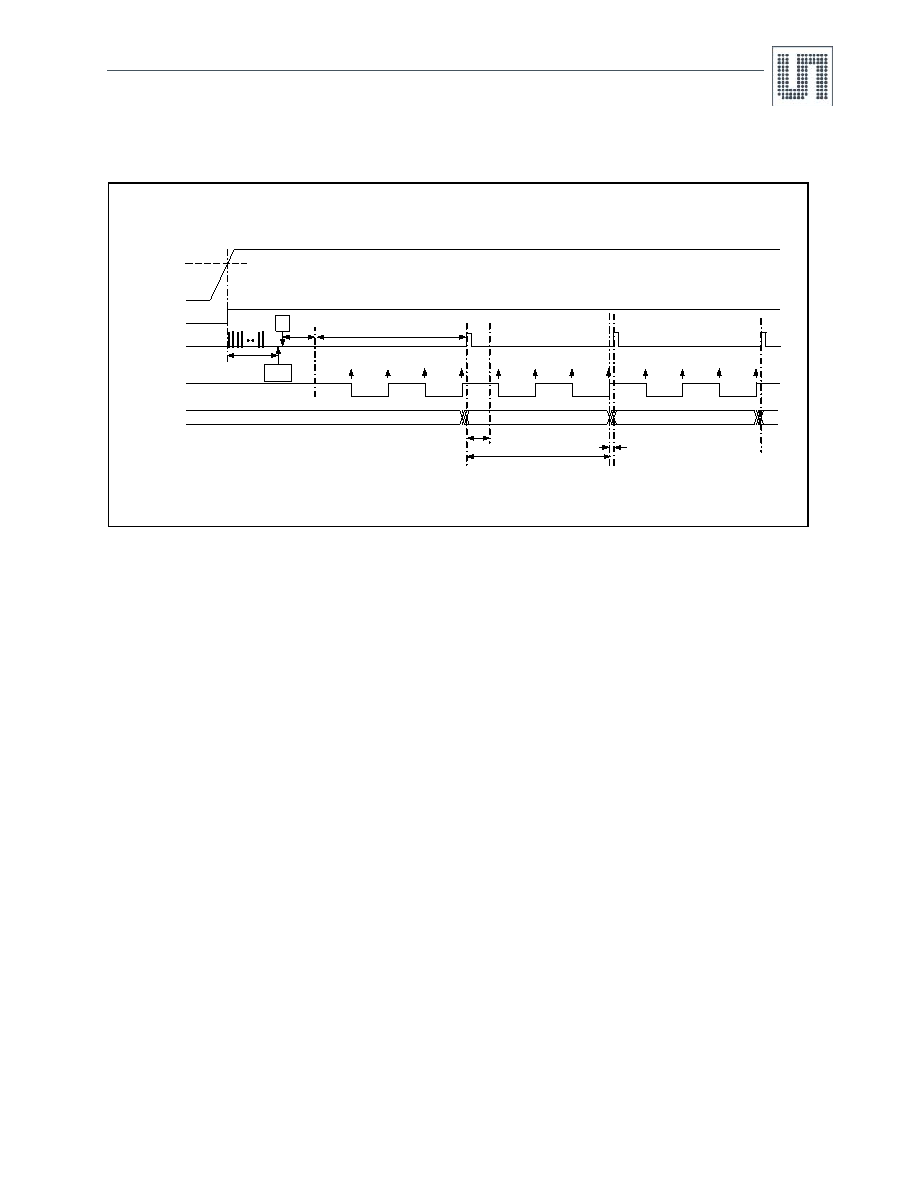
7.9.2 Initialization Sequence at Power ON
Figure 16. AS8510 Device Initialization Sequence at Power ON
Device initialization starts if the DVDD and AVDD supplies are switched ON and DVDD > VPORHID. The duration period of Initialization is 500
μsec
and during this period, INT pin toggles at the rate of internal low power oscillator. Toggling on INT during the period of initialization should be
ignored in the system. Device configuration and activation should be carried out only after the initialization period.
On ADC start, device enters into analog stabilization state and takes 1.5msec for oscillator and Reference to settle. After this 1.5msec period, the
first interrupt will occur after a time period of TADC.
TDATA_STATUS_RD is the time period during which the micro-controller should complete reading of data and status from the device. If reading is
carried out beyond this time period, then, ADC performance will degrade for next sample generation. Status register gets cleared automatically
only when micro-controller reads this register. Data in the channel registers is changed after TDATA_VALID duration. Ensure that data channel
registers and status registers are not read during the TDATA_INVALID duration.
Example:
Configuration registers are set as follows:
CLK_REG = 8’b0010_0000
DEC_REG_R1_I = 0100_0101
DEC_REG_R2_I = 1100_0101
FIR_CTL_REG_I = 0000_0100
ADC is configured to a data rate of 1KHz, CHOP_CLK to 2KHz, and Modulator clock to 1MHz, Decimation ratio of CIC1 = 64, and Decimation
ratio of CIC2 = 4. With these settings the various time periods as shown in the Figure 16 are as follows:
TDATA_STATUS_RD = 100
μsec
(TDATA_STATUS_RD = (1/mod_clk) * R1 * [((mod_clk/(2*chop_clk))*(1/R1)) - 2.5)
TDATA_INVALID = 8
μsec
TADC = 1msec
TDATA_VALID = TADC - TDATA_INVALID = 1msec - 8
μsec
CHOP_CLK and POR_N are internal signals of the device.
Configure
Device
Start
ADC
DVDD/AVDD
POR_N
INT
CHOP_CLK
Channel Data
Register
0x0000
DATA1
DATA2
D1
D2
D3
D4
D1
D2
D3
D4
D1
D2
D3
D4
500S
1.5mS
TDATA_STATUS_RD
TDATA_VALID
TDATA_INVALID
VPORHID/VPORHIA
TADC
相关PDF资料 |
PDF描述 |
|---|---|
| AS8530-ASOT-002-500 | IC TXRX LIN COMPANION 8-SOIC |
| AS8530A-ASOT-500 | IC SYSTEM BASIS CHIP 8-SOIC |
| AT17F080-30TQI | IC FLASH CONFIG 8M 44TQFP |
| AT17F080A-30QI | IC FLASH CONFIG 8M 32TQFP |
| AT17F16-30TQI | IC FLASH CONFIG 16M 44TQFP |
相关代理商/技术参数 |
参数描述 |
|---|---|
| AS8510-ASST-500 | 功能描述:IC BATTERY MANAGEMENT 20-SSOP RoHS:是 类别:集成电路 (IC) >> 接口 - 传感器和探测器接口 系列:- 其它有关文件:Automotive Product Guide 产品培训模块:Lead (SnPb) Finish for COTS Obsolescence Mitigation Program 标准包装:74 系列:- 类型:触控式传感器 输入类型:数字 输出类型:数字 接口:JTAG,串行 电流 - 电源:100µA 安装类型:表面贴装 封装/外壳:20-TSSOP(0.173",4.40mm 宽) 供应商设备封装:20-TSSOP 包装:管件 |
| AS8510-COPPER-SHUNT | 功能描述:DEMO BOARD FOR AS8510 制造商:ams 系列:- 零件状态:在售 主要用途:接口,数据捕捉 嵌入式:- 使用的 IC/零件:AS8510 主要属性:- 辅助属性:图形用户界面 所含物品:板 标准包装:1 |
| AS8510-DB | 制造商:ams 功能描述:AS8510 Demo Board |
| AS8515-ZMFM | 制造商:ams 功能描述:IC BATTERY MANAGEMENT 制造商:ams 功能描述:Data Acquisition System w/ Power Management and LIN Transceiver - MLF-32 制造商:ams 功能描述:T&R / MLF 32 (5x5) |
| AS8515-ZMFP | 制造商:ams 功能描述:IC INTERFACE TRANSCEIVER 制造商:ams 功能描述:T&R / MLF 32 (5x5) |
发布紧急采购,3分钟左右您将得到回复。