参数资料
| 型号: | BR24L16-W |
| 厂商: | Rohm Semiconductor |
| 文件页数: | 17/41页 |
| 文件大小: | 0K |
| 描述: | IC EEPROM 16KBIT 400KHZ 8DIP |
| 标准包装: | 2,000 |
| 格式 - 存储器: | EEPROMs - 串行 |
| 存储器类型: | EEPROM |
| 存储容量: | 16K (2K x 8) |
| 速度: | 400kHz |
| 接口: | I²C,2 线串口 |
| 电源电压: | 1.8 V ~ 5.5 V |
| 工作温度: | -40°C ~ 85°C |
| 封装/外壳: | 8-DIP(0.300",7.62mm) |
| 供应商设备封装: | 8-DIP |
| 包装: | 管件 |
| 产品目录页面: | 1379 (CN2011-ZH PDF) |
第1页第2页第3页第4页第5页第6页第7页第8页第9页第10页第11页第12页第13页第14页第15页第16页当前第17页第18页第19页第20页第21页第22页第23页第24页第25页第26页第27页第28页第29页第30页第31页第32页第33页第34页第35页第36页第37页第38页第39页第40页第41页
�� �
�
�BR24L� □□� -W� Series,BR24S� □□□� -W� Series�
�Technical� Note�
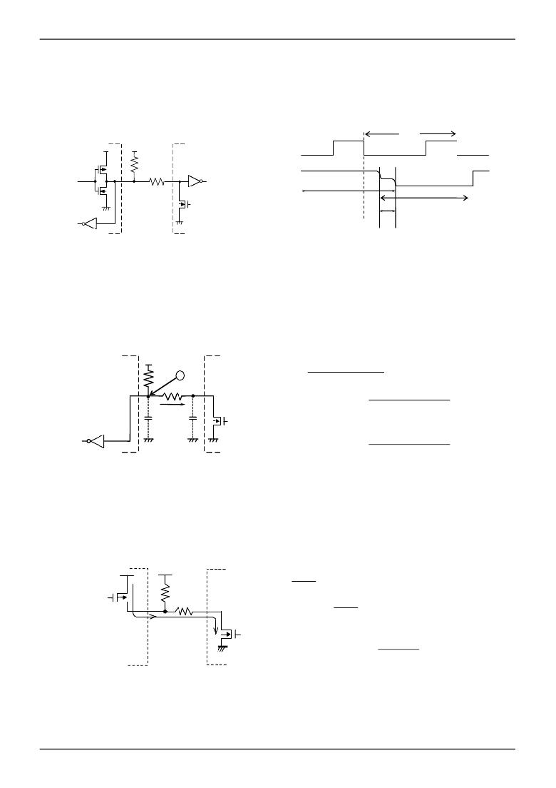
�In� I� C� BUS,� it� is� recommended� that� SDA� port� is� of� open� drain� input/output.� However,� when� to� use� CMOS� input� /� output� of�
�●� Cautions� on� microcontroller� connection�
�Rs�
�2�
�tri� state� to� SDA� port,� insert� a� series� resistance� Rs� between� the� pull� up� resistance� Rpu� and� the� SDA� terminal� of� EEPROM.�
�This� is� controls� over� current� that� occurs� when� PMOS� of� the� microcontroller� and� NMOS� of� EEPROM� are� turned� ON�
�simultaneously.� Rs� also� plays� the� role� of� protection� of� SDA� terminal� against� surge.� Therefore,� even� when� SDA� port� is�
�open� drain� input/output,� Rs� can� be� used.�
�ACK�
�SCL�
�R� PU�
�R� S�
�SDA�
�'H'� output� of� microcontroller�
�'L'� output� of� EEPROM�
�Microcontroller�
�EEPROM�
�Over� current� flows� to� SDA� line� by� 'H'�
�output� of� microcontroller� and� 'L'�
�output� of� EEPROM.�
�Fig.53� I/O� circuit� diagram�
�Fig.54� Input� /� output� collision� timing�
�○� Maximum� value� of� Rs�
�The� maximum� value� of� Rs� is� determined� by� the� following� relations.�
�(1)SDA� rise� time� to� be� determined� by� the� capacity� (CBUS)� of� bus� line� of� Rpu� and� SDA� should� be� tR� or� below.�
�And� AC� timing� should� be� satisfied� even� when� SDA� rise� time� is� late.�
�(2)The� bus� electric� potential� A� to� be� determined� by� Rpu� and� Rs� the� moment� when� EEPROM� outputs� 'L'� to� SDA� bus�
�should� sufficiently� secure� the� input� 'L'� level� (V� IL� )� of� microcontroller� including� recommended� noise� margin� 0.1Vcc.�
�V� CC�
�R� PU�
�A�
�(V� CC� -� V� OL� )×R� S�
�R� PU� +R� S�
�+�
�V� OL� +0.1V� CC� ≦� V� IL�
�R� S�
�I� OL�
�V� OL�
�∴�
�R� S�
�≦�
�V� IL� -� V� OL� -� 0.1V� CC�
�1.1V� CC� -� V� IL�
��
�R� PU�
�Bus� line�
�capacity� CBUS�
�Example)� When� V� CC� =3V,� VIL=0.3V� CC� ,� V� OL� =0.4V,� R� PU� =20k� ?�
�V� IL�
�Microcontroller�
�EEPROM�
�from(2),�
�R� S�
�≦�
�≦�
�0.3×3� -� 0.4� -� 0.1×3�
�1.1×3� -� 0.3×3�
�1.67� [� k� ?� ]�
��
�20×10� 3�
�Fig.55� I/O� circuit� diagram�
�○� Minimum� value� of� Rs�
�The� minimum� value� of� Rs� is� determined� by� over� current� at� bus� collision.� When� over� current� flows,� noises� in� power� source�
�line,� and� instantaneous� power� failure� of� power� source� may� occur.� When� allowable� over� current� is� defined� as� I,� the�
�following� relation� must� be� satisfied.� Determine� the� allowable� current� in� consideration� of� impedance� of� power� source� line�
�in� set� and� so� forth.� Set� the� over� current� to� EEPROM� 10mA� or� below.�
�R� PU�
�R� S�
�'L'� output�
�∴�
�V� CC�
�R� S�
�R� S�
�≦�
�≧�
�I�
�V� CC�
�I�
�Over� current� Ⅰ�
�Example)When� V� CC� =3V,� I=10mA�
�10×10�
�'H'� output�
�Microcontroller�
�EEPROM�
�R� S�
�≧�
�≧�
�3�
�-3�
�300� [� ?� ]�
�Fig.56� I/O� circuit� diagram�
�www.rohm.com�
�?� 2009� ROHM� Co.,� Ltd.� All� rights� reserved.�
�17/40�
�2009.09� -� Rev.D�
�相关PDF资料 |
PDF描述 |
|---|---|
| AGLN250V2-VQ100I | IC FPGA NANO 1KB 250K 100VQFP |
| AGLN250V2-ZVQ100I | IC FPGA NANO 1KB 250K 100VQFP |
| EP1K10QC208-1N | IC ACEX 1K FPGA 10K 208-PQFP |
| EP1K10QC208-1 | IC ACEX 1K FPGA 10K 208-PQFP |
| BR25S256FJ-WE2 | IC EEPROM SPI 256KB 20MHZ 8-SOP |
相关代理商/技术参数 |
参数描述 |
|---|---|
| BR24L256FJ-WE2 | 制造商:ROHM 制造商全称:Rohm 功能描述:High Reliability Series EEPROMs I2C BUS |
| BR24L256FJ-WTR | 制造商:ROHM 制造商全称:Rohm 功能描述:High Reliability Series EEPROMs I2C BUS |
| BR24L256FVJ-WE2 | 制造商:ROHM 制造商全称:Rohm 功能描述:High Reliability Series EEPROMs I2C BUS |
| BR24L256FVJ-WTR | 制造商:ROHM 制造商全称:Rohm 功能描述:High Reliability Series EEPROMs I2C BUS |
| BR24L256FVM-WE2 | 制造商:ROHM 制造商全称:Rohm 功能描述:High Reliability Series EEPROMs I2C BUS |
发布紧急采购,3分钟左右您将得到回复。