- 您现在的位置:买卖IC网 > PDF目录298892 > BX80524P366128 (INTEL CORP) 32-BIT, 366 MHz, MICROPROCESSOR, PPGA370 PDF资料下载
参数资料
| 型号: | BX80524P366128 |
| 厂商: | INTEL CORP |
| 元件分类: | 微控制器/微处理器 |
| 英文描述: | 32-BIT, 366 MHz, MICROPROCESSOR, PPGA370 |
| 封装: | 1.950 X 1.950 INCH, HEAT SINK, STAGGERED, PLASTIC, PGA-370 |
| 文件页数: | 13/88页 |
| 文件大小: | 1622K |
| 代理商: | BX80524P366128 |
第1页第2页第3页第4页第5页第6页第7页第8页第9页第10页第11页第12页当前第13页第14页第15页第16页第17页第18页第19页第20页第21页第22页第23页第24页第25页第26页第27页第28页第29页第30页第31页第32页第33页第34页第35页第36页第37页第38页第39页第40页第41页第42页第43页第44页第45页第46页第47页第48页第49页第50页第51页第52页第53页第54页第55页第56页第57页第58页第59页第60页第61页第62页第63页第64页第65页第66页第67页第68页第69页第70页第71页第72页第73页第74页第75页第76页第77页第78页第79页第80页第81页第82页第83页第84页第85页第86页第87页第88页
Intel Celeron Processor
20
Datasheet
DC tables. Extended exposure to the maximum ratings may affect device reliability. Furthermore,
although the processor contains protective circuitry to resist damage from static electric discharge,
one should always take precautions to avoid high static voltages or electric fields.
NOTES:
1. Operating voltage is the voltage to which the component is designed to operate. See Table 4.
2. This rating applies to the VCC
CORE, VCC5, and any input (except as noted below) to the processor.
3. Parameter applies to CMOS, APIC, and TAP bus signal groups only.
4. The electrical and mechanical integrity of the processor edge fingers are specified to last for 50 insertion/
extraction cycles.
5. S.E.P. Package Only
6. PPGA Package Only
2.10
Processor DC Specifications
The processor DC specifications in this section are defined for the Intel Celeron processor. See
Section 7.0 for signal definitions and Section 5.0 for signal listings.
Most of the signals on the Intel Celeron processor system bus are in the AGTL+ signal group.
These signals are specified to be terminated to 1.5 V. The DC specifications for these signals are
listed in Table 5.
To allow connection with other devices, the Clock, CMOS, APIC, and TAP signals are designed to
interface at non-AGTL+ levels. The DC specifications for these pins are listed in Table 6.
Intel Celeron processor system bus frequencies. Specifications are valid only while meeting
specifications for case temperature, clock frequency, and input voltages. Care should be taken to
read all notes associated with each parameter.
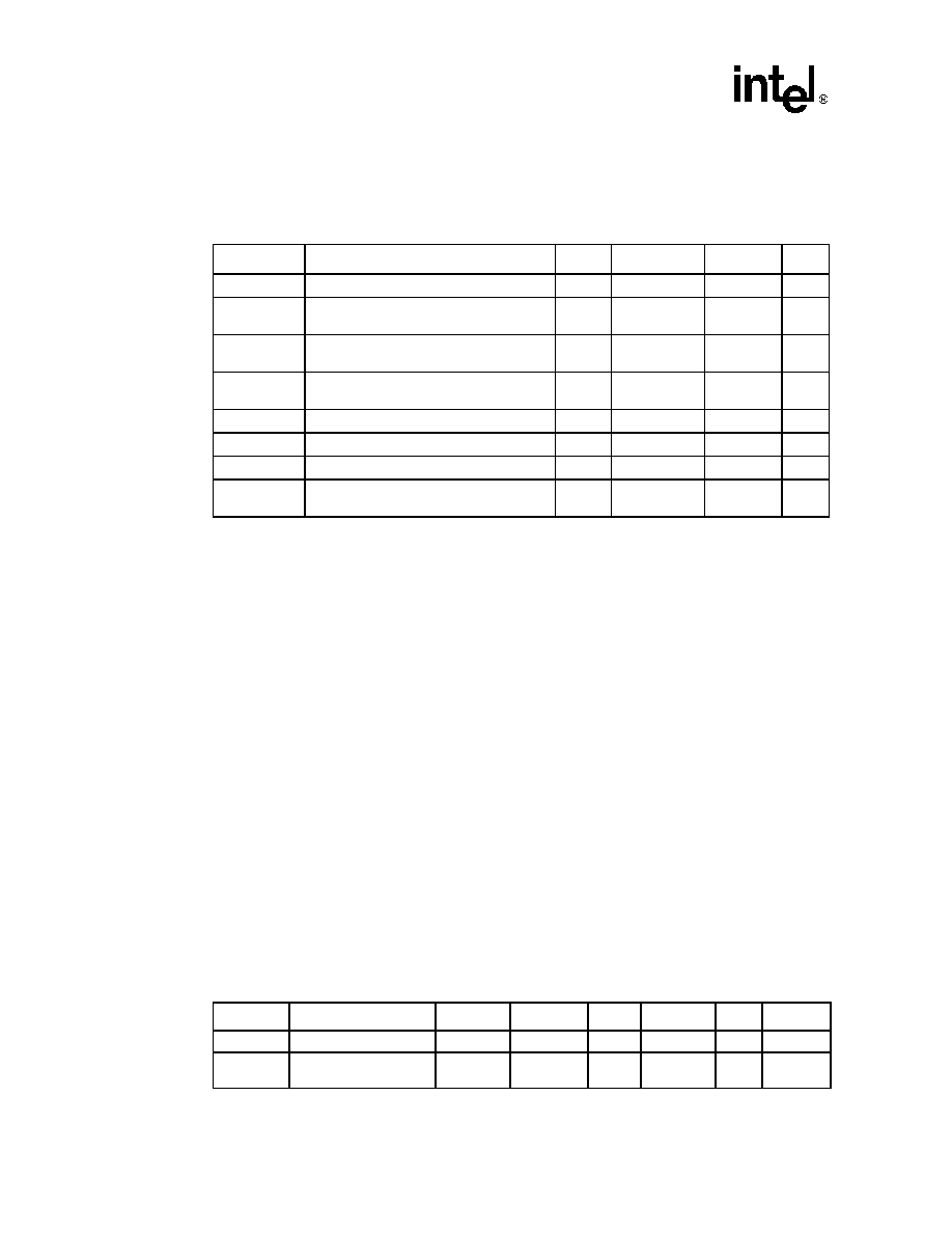
Table 3.
Intel Celeron Processor Absolute Maximum Ratings
Symbol
Parameter
Min
Max
Unit
Notes
TSTORAGE
Processor storage temperature
–40
85
°C
VCC(All)
Any processor supply voltage with respect
to VSS
–0.5
Operating
voltage + 1.0
V
1, 2
VinAGTL+
AGTL+ buffer DC input voltage with respect
to VSS
–0.3
VCC
CORE + 0.7
V
VinCMOS
CMOS buffer DC input voltage with respect
to VSS
–0.3
3.3
V
3
IVID
Max VID pin current
5
mA
ISLOTOCC
Max SLOTOCC# pin current
5
mA
5
ICPUPRES
Max CPUPRES# pin current
5
mA
6
Mech Max
Edge Fingers5
Mechanical integrity of processor edge
fingers
50
Insertions/
Extractions
4, 5
Table 4.
Intel Celeron Processor Voltage and Current Specifications 1
Symbol
Parameter
Core Freq
Min
Typ
Max
Unit
Notes
VCC
CORE
VCC for processor core
2.00
V
2, 3, 4
VREF
AGTL+ input reference
voltage
2/
3VTT – 2%
2/
3VTT + 2%
V
± 2%, 11
相关PDF资料 |
PDF描述 |
|---|---|
| BX80524P300000 | 32-BIT, 300 MHz, MICROPROCESSOR, PPGA370 |
| BX80525U500512E | 32-BIT, 500 MHz, MICROPROCESSOR, XMA |
| BX80525U533512E | 32-BIT, 533 MHz, MICROPROCESSOR, XMA |
| BX80525U550512E | 32-BIT, 550 MHz, MICROPROCESSOR, XMA |
| BX80525U450512E | 32-BIT, 450 MHz, MICROPROCESSOR, XMA |
相关代理商/技术参数 |
参数描述 |
|---|---|
| BX80524R30012A | 制造商:未知厂家 制造商全称:未知厂家 功能描述:32-Bit Microprocessor |
| BX80524R33312A | 制造商:未知厂家 制造商全称:未知厂家 功能描述:32-Bit Microprocessor |
| BX80525U500256E | 制造商:未知厂家 制造商全称:未知厂家 功能描述:Microprocessor |
| BX80525U533256EB | 制造商:未知厂家 制造商全称:未知厂家 功能描述:Microprocessor |
| BX80525U550256E | 制造商:未知厂家 制造商全称:未知厂家 功能描述:Microprocessor |
发布紧急采购,3分钟左右您将得到回复。