- 您现在的位置:买卖IC网 > PDF目录16834 > CDB5464U (Cirrus Logic Inc)BOARD EVAL FOR CS5464 ADC PDF资料下载
参数资料
| 型号: | CDB5464U |
| 厂商: | Cirrus Logic Inc |
| 文件页数: | 40/46页 |
| 文件大小: | 0K |
| 描述: | BOARD EVAL FOR CS5464 ADC |
| 标准包装: | 1 |
| 主要目的: | 电源管理,电度表/功率表 |
| 嵌入式: | 是,MCU,8 位 |
| 已用 IC / 零件: | CS5464 |
| 主要属性: | 电能表 |
| 次要属性: | 图形用户接口,SPI? 和 USB 接口 |
| 已供物品: | 板,线缆,软件 |
| 产品目录页面: | 754 (CN2011-ZH PDF) |
| 相关产品: | CS5464-ISZR-ND - IC ENERGY METERING 1PHASE 28SSOP 598-1194-5-ND - IC ENERGY METERING 1PHASE 28SSOP 598-1193-5-ND - IC PWR/ENERGY METER 3CH 28-SSOP |
| 其它名称: | 598-1554 CDB-5464U |
第1页第2页第3页第4页第5页第6页第7页第8页第9页第10页第11页第12页第13页第14页第15页第16页第17页第18页第19页第20页第21页第22页第23页第24页第25页第26页第27页第28页第29页第30页第31页第32页第33页第34页第35页第36页第37页第38页第39页当前第40页第41页第42页第43页第44页第45页第46页
�� �
�
�CS5464�
�9.1.2� Gain� Calibration�
�During� gain� calibration,� a� full-scale� reference� signal�
�must� be� applied� to� the� meter� or� optionally,� scaled� to� the�
�VIN� ?� ,� ?� IIN1� ?� (IIN2� ???� pins� of� the� CS5464.� A� DC� reference�
�must� be� used� for� DC� gain� calibration.� Either� an� AC� or�
�DC� reference� can� be� used� for� RMS� AC� calibrations.� If�
�DC� is� used,� the� associated� high-pass� filter� (HPF)� must�
�be� off.�
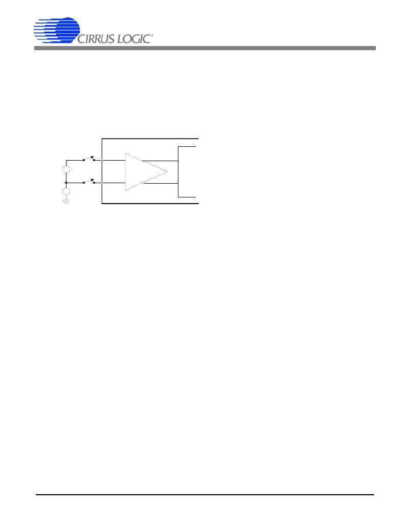
�Figure� 12� shows� the� basic� setup� for� gain� calibration.�
�External�
�Connections�
�During� AC� gain� calibration� the� RMS� level� of� the� applied�
�reference� is� measured� with� the� preset� gain,� then� divided�
�into� 0.6� and� the� quotient� stored� back� into� the� corre-�
�sponding� gain� register.�
�9.1.2.2� DC� Gain� Calibration�
�With� a� DC� reference� applied,� the� DC� Gain� Calibration�
�command� measures� and� averages� DC� values� read� on�
�the� specified� voltage� or� current� channels� and� stores� the�
�reciprocal� result� in� the� associated� gain� registers,� con-�
�verting� measured� voltage� into� needed� gain.� Subse-�
�quent� conversions� will� use� the� new� gain� value.�
�-�
�-�
�R� eference�
�Signal�
�CM�
�+�
�+�
�IN+�
�IN-�
�+�
�-�
�XG� AIN�
�+�
�-�
�9.1.3� Calibration� Order�
�1.� DC� offset.�
�2.� DC� or� AC� gain.�
�3.� AC� offset� (if� needed).�
�If� both� AC� gain� and� offset� calibrations� were� performed,�
�Figure� 12.� System� Calibration� of� Gain.�
�Using� a� reference� that� is� too� large� or� too� small� can�
�cause� an� over-range� condition� during� calibration.� Either�
�condition� can� set� Status� register� bits� I1OR� (I2OR)�
�V1OR� (V2OR)� for� DC� and� I1ROR� (I2ROR)� V1ROR�
�(V2ROR)� for� AC� calibration.�
�Full� scale� (FS)� for� the� voltage� input� is� ±250mV� peak� and�
�for� the� current� inputs� is� ±250mV� or� ±50mV� peak� de-�
�pending� on� selected� gain� range.� The� normal� peak� volt-�
�age� applied� to� these� pins� should� not� exceed� these�
�levels� during� calibration� or� normal� operation.�
�The� range� of� the� gain� registers� limits� the� gain� calibration�
�range� and� subsequently� the� range� of� the� reference� level�
�that� can� be� applied.� The� reference� should� not� exceed�
�FS� or� be� lower� than� FS/4.�
�9.1.2.1� AC� Gain� Calibration�
�Full� scale� for� AC� RMS� gain� calibrations� is� 60%� of� the� in-�
�put’s� full-scale� range,� which� is� either� 250mV� or� 50mV�
�depending� on� the� gain� range� selected.� That’s� 150mV� or�
�30mV,� again� depending� on� range.� So� the� normal� refer-�
�ence� input� level� should� be� either� 150� or� 30� mV� RMS� ,� AC�
�or� DC.�
�Prior� to� executing� an� AC� Gain� Calibration� command,�
�gain� registers� for� any� channel� to� be� calibrated� should� be�
�set� to� 1.0� if� the� reference� level� mentioned� above� is�
�used,� or� to� that� level� divided� by� the� actual� reference� lev-�
�el� used.�
�40�
�it� is� possible� to� repeat� both� to� obtain� additional� accuracy�
�as� AC� gain� and� offset� may� interact.�
�9.1.4� Temperature� Sensor� Calibration�
�Temperature� sensor� calibration� involves� the� adjustment�
�of� two� parameters� -� ?� V� BE� and� V� BE� 0.� These� values� must�
�be� known� in� order� to� calibrate� the� temperature� sensor.�
�See� Section� 6.13� Temperature� Measurement� on� page�
�21� for� an� explanation� of� ?� V� BE� and� V� BE� 0� and� how� to� cal-�
�culate� T� GAIN� and� T� OFF� register� values� from� them.�
�9.1.4.1� Temperature� Offset� Calibration�
�Offset� calibration� can� be� done� at� any� temperature,� but�
�should� be� done� mid-scale� if� any� gain� error� exists.�
�Subtract� the� measured� T� register� temperature� from� the�
�actual� temperature� to� determine� the� offset� error.� Multi-�
�ply� this� error� by� ?� V� BE� and� add� it� to� V� BE� 0� to� yield� a� new�
�V� BE� 0� value.� Recalculate� T� OFF� using� this� new� value� .�
�9.1.4.2� Temperature� Gain� Calibration�
�Two� temperature� points� far� enough� apart� to� give� rea-�
�sonable� accuracy,� for� example� 25°C� and� 85°C,� are� re-�
�quired� to� calibrate� temperature� gain.�
�Divide� the� actual� temperature� difference� by� the� mea-�
�sured� (� T� register)� difference� for� the� two� temperatures.�
�This� gives� a� gain� correction� factor.� Update� the� T� GAIN�
�register� by� multiplying� it’s� value� by� this� correction� factor.�
�Update� ?� V� BE� by� dividing� its� old� value� by� the� gain� cor-�
�rection� factor.� It� will� be� needed� for� subsequent� offset�
�calibrations.�
�DS682F3�
�相关PDF资料 |
PDF描述 |
|---|---|
| H6MMS-2618M | DIP CABLE - HDM26S/AE26M/HDM26S |
| MAX6126A41+T | IC VREF SERIES PREC 4.096V 8UMAX |
| H1DXH-3436G | IDC CABLE - HKR34H/AE34G/X |
| PCMB104T-2R0MS | COIL 2.0 UH POWER CHOKE 20% SMD |
| MAX6126A30+T | IC VREF SERIES PREC 3V 8-UMAX |
相关代理商/技术参数 |
参数描述 |
|---|---|
| CDB5464U-Z | 制造商:Cirrus Logic 功能描述:EVAL BD PB-FREE DEMO BOARD FOR CS5464 - Boxed Product (Development Kits) 制造商:Cirrus Logic 功能描述:Eval Board |
| CDB5466U | 功能描述:数据转换 IC 开发工具 Eval Bd F/Residental Pow-Meter Apps RoHS:否 制造商:Texas Instruments 产品:Demonstration Kits 类型:ADC 工具用于评估:ADS130E08 接口类型:SPI 工作电源电压:- 6 V to + 6 V |
| CDB5466U-Z | 制造商:Cirrus Logic 功能描述:PB-FREEEVAL BOARD FOR CS5466 WITH USB - Bulk |
| CDB5467U | 功能描述:数据转换 IC 开发工具 Eval Bd 4-Ch Sngl-Phs Pow/Energy RoHS:否 制造商:Texas Instruments 产品:Demonstration Kits 类型:ADC 工具用于评估:ADS130E08 接口类型:SPI 工作电源电压:- 6 V to + 6 V |
| CDB5471 | 制造商:Cirrus Logic 功能描述:Tools Development kit Kit Con |
发布紧急采购,3分钟左右您将得到回复。