- 您现在的位置:买卖IC网 > PDF目录380066 > CS4215-KQ (CIRRUS LOGIC INC) 16-Bit Multimedia Audio Codec PDF资料下载
参数资料
| 型号: | CS4215-KQ |
| 厂商: | CIRRUS LOGIC INC |
| 元件分类: | 消费家电 |
| 英文描述: | 16-Bit Multimedia Audio Codec |
| 中文描述: | SPECIALTY CONSUMER CIRCUIT, PQFP100 |
| 封装: | TQFP-100 |
| 文件页数: | 25/52页 |
| 文件大小: | 878K |
| 代理商: | CS4215-KQ |
第1页第2页第3页第4页第5页第6页第7页第8页第9页第10页第11页第12页第13页第14页第15页第16页第17页第18页第19页第20页第21页第22页第23页第24页当前第25页第26页第27页第28页第29页第30页第31页第32页第33页第34页第35页第36页第37页第38页第39页第40页第41页第42页第43页第44页第45页第46页第47页第48页第49页第50页第51页第52页
Power Down Mode
Bringing the PDN pin high puts the CS4215 into
the power down mode. In this mode HEADC
and CMOUT will not supply current. Power
down will change all the control registers to the
reset state shown under each Control Time Slot
register. In the power down mode, the TSOUT
pin will follow the TSIN state with less than
10 ns delay.
After returning to normal operation from power
down, an offset calibration cycle must be exe-
cuted. Either bringing RESET low then high, or
updating the control registers, will cause an off-
set calibration cycle. In either case, a delay of
50 ms must occur after PDN goes low before
executing the offset calibration. This allows the
internal voltage reference time to settle.
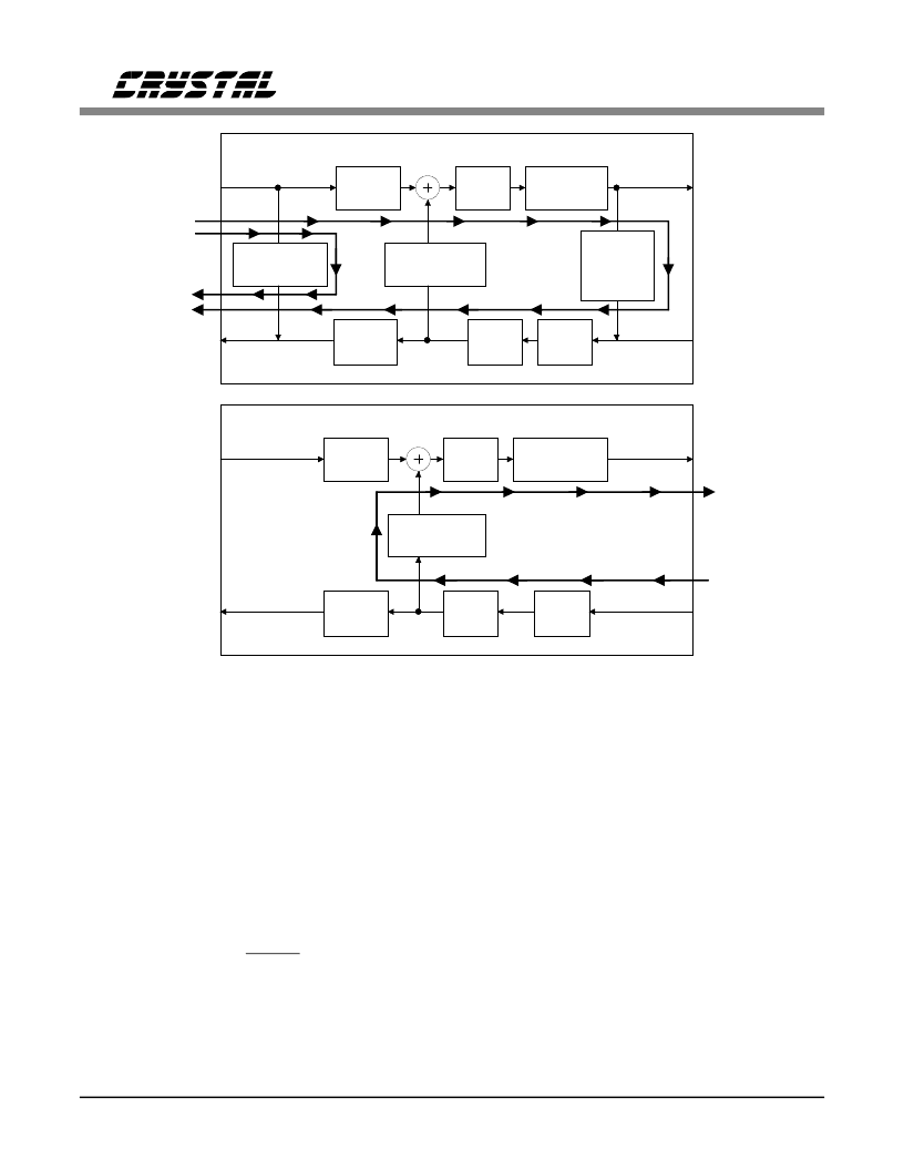
LOOPBACK TEST MODES
The CS4215 contains three loopback modes that
may be used to test the codec. Two of the loop-
back test modes are designed to allow the host to
perform a self-test on the CS4215. The third
mode allows laboratory testing using external
equipment.
Host Self-Test Loopback Modes
Since the CS4215 is a mixed-signal device, it is
equipped with an internal register that will en-
able the host to perform a two-tiered test on
power-up or as needed. The loopback test is en-
abled by setting the Enable Loopback bit, ENL,
in control register 4. The first tier of loopback is
a digital-digital loopback, DD, which is selected
by clearing the DAD bit in control register 4 (see
SDOUT
A/
μ
Decode
Digital-
Analog-
Digital
Loopback
Gain
Attenuation
D/A
A/D
Digital-Digital
Loopback
SDIN
LOUT
ROUT
LIN
RIN
DAD
DD
CS4215
SDOUT
A/
μ
Decode
Gain
Attenuation
D/A
A/D
A/
μ
Encode
SDIN
LOUT
ROUT
LIN
RIN
CS4215
Monitor = 0
ADA
Monitor = 1111
(Full Mute)
(Still Operate)
(Disconnected)
(DAC data = 0)
0 is different for
each data
format
A/
μ
Encode
Figure 16. DD, DAD & ADA Loopback Paths
CS4215
DS76F2
25
相关PDF资料 |
PDF描述 |
|---|---|
| CS4215 | 16-Bit Multimedia Audio Codec |
| CS4216 | 16-Bit Stereo Audio Codec |
| CS4216-KL | IC EEPROM SRL 256-8BIT 8DIP |
| CS4216-KQ | 16-Bit Stereo Audio Codec |
| CS4218-KL | 16-Bit Stereo Audio Codec |
相关代理商/技术参数 |
参数描述 |
|---|---|
| CS4216 | 制造商:CIRRUS 制造商全称:Cirrus Logic 功能描述:16-Bit Stereo Audio Codec |
| CS4216-KL | 制造商:Rochester Electronics LLC 功能描述:- Bulk |
| CS4216-KQ | 制造商:CIRRUS 制造商全称:Cirrus Logic 功能描述:16-Bit Stereo Audio Codec |
| CS4217-KL | 制造商:CRYSTAL 功能描述: |
| CS4218 | 制造商:CIRRUS 制造商全称:Cirrus Logic 功能描述:16-Bit Stereo Audio Codec |
发布紧急采购,3分钟左右您将得到回复。