- 您现在的位置:买卖IC网 > Datasheet目录322 > DS2704G+T&R (Maxim Integrated Products)IC EEPROM 1.25KBIT 6TDFN Datasheet资料下载
参数资料
| 型号: | DS2704G+T&R |
| 厂商: | Maxim Integrated Products |
| 文件页数: | 11/18页 |
| 文件大小: | 0K |
| 描述: | IC EEPROM 1.25KBIT 6TDFN |
| 产品培训模块: | Lead (SnPb) Finish for COTS Obsolescence Mitigation Program |
| 标准包装: | 10,000 |
| 格式 - 存储器: | EEPROMs - 串行 |
| 存储器类型: | EEPROM |
| 存储容量: | 1.25K(32B x 5 页) |
| 接口: | 1 线 串行 |
| 电源电压: | 2.5 V ~ 5.5 V |
| 工作温度: | -30°C ~ 85°C |
| 封装/外壳: | 6-WDFN 裸露焊盘 |
| 供应商设备封装: | 6-TDFN 裸露焊盘(3x3) |
| 包装: | 带卷 (TR) |
�� �
�
�DS2704:� 1280-Bit� EEPROM� with� SHA-1� Authentication�
�CRC� GENERATION�
�The� DS2704� has� an� 8-bit� CRC� stored� in� the� most� significant� byte� of� its� 1-Wire� net� address� and� generates� a� CRC�
�during� some� command� protocols.� To� ensure� error-free� transmission� of� the� address,� the� host� system� can� compute� a�
�CRC� value� from� the� first� 56� bits� of� the� address� and� compare� it� to� the� CRC� from� the� DS2704.�
�The� host� system� is� responsible� for� verifying� the� CRC� value� and� taking� action� as� a� result.� The� DS2704� does� not�
�compare� CRC� values� and� does� not� prevent� a� command� sequence� from� proceeding� as� a� result� of� a� CRC� mismatch.�
�Proper� use� of� the� CRC� can� result� in� a� communication� channel� with� a� very� high� level� of� integrity.�
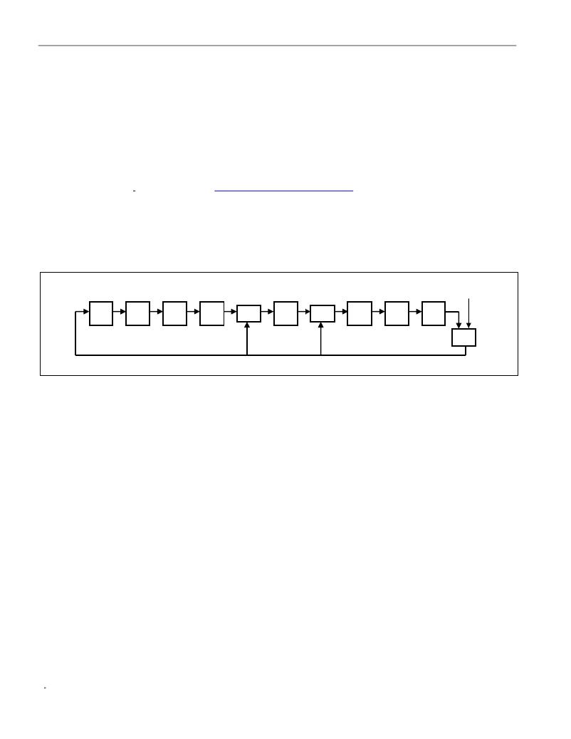
�The� CRC� can� be� generated� by� the� host� using� a� circuit� consisting� of� a� shift� register� and� XOR� gates� as� shown� in�
�Figure� 3,� or� it� can� be� generated� in� software� using� the� polynomial� X� 8� +� X� 5� +� X� 4� +� 1.� Additional� information� about� the�
�Dallas� 1-Wire� CRC� is� available� in� Application� Note� 27:� Understanding� and� Using� Cyclic� Redundancy� Checks� with�
�Dallas� Semiconductor� iButton� ?� Products� (� www.maxim-ic.com/appnoteindex� ).�
�In� the� circuit� in� Figure� 3,� the� shift� register� bits� are� initialized� to� 0.� Then,� starting� with� the� least� significant� bit� of� the�
�family� code,� one� bit� at� a� time� is� shifted� in.� After� the� 8th� bit� of� the� family� code� has� been� entered,� then� the� serial�
�number� is� entered.� After� the� 48th� bit� of� the� serial� number� has� been� entered,� the� shift� register� contains� the� CRC�
�value.�
�Figure� 3.� 1-Wire� CRC� Generation� Block� Diagram�
�INPUT�
�MSb�
�XOR�
�XOR�
�LSb�
�XOR�
�During� some� command� sequences,� the� DS2704� also� generates� an� 8-bit� CRC� and� provides� this� value� to� the� bus�
�master� to� facilitate� validation� for� the� transfer� of� command,� address,� and� data� from� the� bus� master� to� the� DS2704.�
�The� DS2704� computes� an� 8-bit� CRC� for� the� command� and� address� bytes� received� from� the� bus� master� for� the�
�Read� Memory,� Read� Status� and� Read/Generate� CRC� commands� to� confirm� that� these� bytes� have� been� received�
�correctly.� The� CRC� generator� on� the� DS2704� is� also� used� to� provide� verification� of� error-free� data� transfer� as� each�
�EEPROM� page� is� sent� to� the� master� during� a� Read� Data/Generate� CRC� command� and� for� the� 8� bytes� of�
�information� in� the� Status� memory� field.�
�In� each� case� where� a� CRC� is� used� for� data� transfer� validation,� the� bus� master� must� calculate� the� CRC� value� using�
�the� same� polynomial� function� and� compare� the� calculated� value� to� the� CRC� either� stored� in� the� DS2704� Net�
�Address� or� computed� by� the� DS2704.� The� comparison� of� CRC� values� and� decision� to� continue� with� an� operation�
�are� determined� entirely� by� the� bus� master.� There� is� no� circuitry� in� the� DS2704� that� prevents� the� a� command�
�sequence� from� proceeding� if� the� stored� or� calculated� CRC� from� the� DS2704� and� the� calculated� CRC� from� the� host�
�do� not� match.�
�HARDWARE� CONFIGURATION�
�Because� the� 1-Wire� bus� has� only� a� single� line,� it� is� important� that� each� device� on� the� bus� be� able� to� drive� it� at� the�
�appropriate� time.� To� facilitate� this,� each� device� attached� to� the� 1-Wire� bus� must� connect� to� the� bus� with� open-drain�
�or� tri-state� output� drivers.� The� DS2704� uses� an� open-drain� output� driver� as� part� of� the� bidirectional� interface�
�circuitry� shown� in� Figure� 4.� If� a� bidirectional� pin� is� not� available� on� the� bus� master,� separate� output� and� input� pins�
�can� be� connected� together.�
�The� 1-Wire� bus� must� have� a� pullup� resistor� at� the� bus-master� end� of� the� bus.� A� value� of� between� 2k� Ω� and� 5k� Ω� is�
�recommended.� The� idle� state� for� the� 1-Wire� bus� is� high.� If,� for� any� reason,� a� bus� transaction� must� be� suspended,�
�the� bus� must� be� left� in� the� idle� state� to� properly� resume� the� transaction� later.� Note� that� if� the� bus� is� left� low� for� more�
�than� t� RSTL� ,� slave� devices� on� the� bus� begin� to� interpret� the� low� period� as� a� reset� pulse,� effectively� terminating� the�
�transaction.�
�iButton� is� a� registered� trademark� of� Dallas� Semiconductor.�
�11� of� 18�
�相关PDF资料 |
PDF描述 |
|---|---|
| DS28CZ04G-4+T | IC EEPROM 4KBIT 400KHZ 12TQFN |
| DS28DG02E-3C+T | IC EEPROM 2KBIT 2MHZ 28TSSOP |
| DS28E04S-100+T | IC EEPROM 4KBIT 16SOIC |
| DS28EC20+T | IC EEPROM 20KBIT TO92-3 |
| DS301X | KWIK-CHG DESIGNATION STRIP SGL |
相关代理商/技术参数 |
参数描述 |
|---|---|
| DS2704K | 功能描述:电可擦除可编程只读存储器 RoHS:否 制造商:Atmel 存储容量:2 Kbit 组织:256 B x 8 数据保留:100 yr 最大时钟频率:1000 KHz 最大工作电流:6 uA 工作电源电压:1.7 V to 5.5 V 最大工作温度:+ 85 C 安装风格:SMD/SMT 封装 / 箱体:SOIC-8 |
| DS2704REVKIT+ | 制造商:Maxim Integrated Products 功能描述:RMS POWER DETECTOR - Boxed Product (Development Kits) |
| DS2704RG+ | 功能描述:电可擦除可编程只读存储器 RoHS:否 制造商:Atmel 存储容量:2 Kbit 组织:256 B x 8 数据保留:100 yr 最大时钟频率:1000 KHz 最大工作电流:6 uA 工作电源电压:1.7 V to 5.5 V 最大工作温度:+ 85 C 安装风格:SMD/SMT 封装 / 箱体:SOIC-8 |
| DS2704RG+T&R | 功能描述:电可擦除可编程只读存储器 RoHS:否 制造商:Atmel 存储容量:2 Kbit 组织:256 B x 8 数据保留:100 yr 最大时钟频率:1000 KHz 最大工作电流:6 uA 工作电源电压:1.7 V to 5.5 V 最大工作温度:+ 85 C 安装风格:SMD/SMT 封装 / 箱体:SOIC-8 |
| DS2704R-K | 功能描述:电可擦除可编程只读存储器 RoHS:否 制造商:Atmel 存储容量:2 Kbit 组织:256 B x 8 数据保留:100 yr 最大时钟频率:1000 KHz 最大工作电流:6 uA 工作电源电压:1.7 V to 5.5 V 最大工作温度:+ 85 C 安装风格:SMD/SMT 封装 / 箱体:SOIC-8 |
发布紧急采购,3分钟左右您将得到回复。