- 您现在的位置:买卖IC网 > PDF目录3856 > DSPIC30F2012-30I/ML (Microchip Technology)IC DSPIC MCU/DSP 12K 28QFN PDF资料下载
参数资料
| 型号: | DSPIC30F2012-30I/ML |
| 厂商: | Microchip Technology |
| 文件页数: | 66/66页 |
| 文件大小: | 0K |
| 描述: | IC DSPIC MCU/DSP 12K 28QFN |
| 产品培训模块: | Serial Communications using dsPIC30F I2C Serial Communications using dsPIC30F SPI Serial Communications using dsPIC30F UART dsPIC30F 12 bit ADC - Part 2 dsPIC30F Addressing Modes - Part 1 dsPIC30F Architecture - Part 1 dsPIC30F DSP Engine & ALU dsPIC30F Interrupts dsPIC30F Motor Control PWM dsPIC Timers Asynchronous Stimulus dsPIC30F Addressing Modes - Part 2 dsPIC30F Architecture - Part 2 dsPIC30F 12-bit ADC Part 1 |
| 标准包装: | 61 |
| 系列: | dsPIC™ 30F |
| 核心处理器: | dsPIC |
| 芯体尺寸: | 16-位 |
| 速度: | 30 MIP |
| 连通性: | I²C,SPI,UART/USART |
| 外围设备: | 欠压检测/复位,POR,PWM,WDT |
| 输入/输出数: | 20 |
| 程序存储器容量: | 12KB(4K x 24) |
| 程序存储器类型: | 闪存 |
| RAM 容量: | 1K x 8 |
| 电压 - 电源 (Vcc/Vdd): | 2.5 V ~ 5.5 V |
| 数据转换器: | A/D 10x12b |
| 振荡器型: | 内部 |
| 工作温度: | -40°C ~ 85°C |
| 封装/外壳: | 28-VQFN 裸露焊盘 |
| 包装: | 管件 |
| 产品目录页面: | 650 (CN2011-ZH PDF) |
| 配用: | AC164322-ND - MODULE SOCKET MPLAB PM3 28/44QFN DV164005-ND - KIT ICD2 SIMPLE SUIT W/USB CABLE |
| 其它名称: | DSPIC30F201230IML |
第1页第2页第3页第4页第5页第6页第7页第8页第9页第10页第11页第12页第13页第14页第15页第16页第17页第18页第19页第20页第21页第22页第23页第24页第25页第26页第27页第28页第29页第30页第31页第32页第33页第34页第35页第36页第37页第38页第39页第40页第41页第42页第43页第44页第45页第46页第47页第48页第49页第50页第51页第52页第53页第54页第55页第56页第57页第58页第59页第60页第61页第62页第63页第64页第65页当前第66页
2010 Microchip Technology Inc.
DS70102K-page 9
dsPIC30F Flash Programming Specification
5.6.3
PROGRAMMING VERIFICATION
Once the data EEPROM is programmed, the contents
of memory can be verified to ensure that the
programming was successful. Verification requires the
data EEPROM to be read back and compared against
the copy held in the programmer’s buffer. The READD
command reads back the programmed data EEPROM.
Alternatively, the programmer can perform the
verification once the entire device is programmed using
a checksum computation, as described in Section 6.8
Note:
TBLRDL instructions executed within a
REPEAT loop must not be used to read
from Data EEPROM. Instead, it is
recommended to use PSV access.
5.7
Configuration Bits Programming
5.7.1
OVERVIEW
The dsPIC30F has Configuration bits stored in seven
16-bit registers. These bits can be set or cleared to
select various device configurations. There are two
types of Configuration bits: system-operation bits and
code-protect bits. The system-operation bits determine
the power-on settings for system-level components
such as the oscillator and Watchdog Timer. The code-
protect bits prevent program memory from being read
and written.
The FOSC Configuration register has three different
register descriptions, based on the device. The FOSC
Configuration
register
description
for
the
dsPIC30F2010 and dsPIC30F6010/6011/6012/6013/
6014 devices are shown in Table 5-4.
Note:
If user software performs an erase opera-
tion on the configuration fuse, it must be
followed by a write operation to this fuse
with the desired value, even if the desired
value is the same as the state of the
erased fuse.
The FOSC Configuration register description for the
dsPIC30F4011/4012 and dsPIC30F5011/5013 devices
is shown in Table 5-5.
The FOSC Configuration register description for
all remaining
devices
(dsPIC30F2011/2012,
dsPIC30F3010/3011/3012/3013,
dsPIC30F3014/
4013, dsPIC30F5015 and dsPIC30F6011A/6012A/
6013A/ 6014A) is shown in Table 5-6. Always use the
correct register descriptions for your target processor.
The FWDT, FBORPOR, FBS, FSS, FGS and FICD
Configuration registers are not device-dependent. The
register descriptions for these Configuration registers
are shown in Table 5-7.
The Device Configuration register maps are shown in
Table 5-8 through Table 5-11.
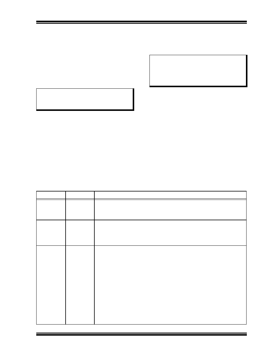
TABLE 5-4:
FOSC CONFIGURATION BITS DESCRIPTION FOR dsPIC30F2010 AND
dsPIC30F6010/6011/6012/6013/6014
Bit Field
Register
Description
FCKSM<1:0>
FOSC
Clock Switching Mode
1x = Clock switching is disabled, Fail-Safe Clock Monitor is disabled
01 = Clock switching is enabled, Fail-Safe Clock Monitor is disabled
00 = Clock switching is enabled, Fail-Safe Clock Monitor is enabled
FOS<1:0>
FOSC
Oscillator Source Selection on POR
11 = Primary Oscillator
10 = Internal Low-Power RC Oscillator
01 = Internal Fast RC Oscillator
00 = Low-Power 32 kHz Oscillator (Timer1 Oscillator)
FPR<3:0>
FOSC
Primary Oscillator Mode
1111 = ECIO w/PLL 16X – External Clock mode with 16X PLL. OSC2 pin is I/O
1110 = ECIO w/PLL 8X – External Clock mode with 8X PLL. OSC2 pin is I/O
1101 = ECIO w/PLL 4X – External Clock mode with 4X PLL. OSC2 pin is I/O
1100 = ECIO – External Clock mode. OSC2 pin is I/O
1011 = EC – External Clock mode. OSC2 pin is system clock output (FOSC/4)
1010 = Reserved (do not use)
1001 = ERC – External RC Oscillator mode. OSC2 pin is system clock output
(FOSC/4)
1000 = ERCIO – External RC Oscillator mode. OSC2 pin is I/O
0111 = XT w/PLL 16X – XT Crystal Oscillator mode with 16X PLL
0110 = XT w/PLL 8X – XT Crystal Oscillator mode with 8X PLL
0101 = XT w/PLL 4X – XT Crystal Oscillator mode with 4X PLL
0100 = XT – XT Crystal Oscillator mode (4 MHz-10 MHz crystal)
001x = HS – HS Crystal Oscillator mode (10 MHz-25 MHz crystal)
000x = XTL – XTL Crystal Oscillator mode (200 kHz-4 MHz crystal)
相关PDF资料 |
PDF描述 |
|---|---|
| ATMEGA16-16PI | IC AVR MCU 16K 16MHZ IND 40-DIP |
| ATMEGA128-16MI | IC AVR MCU 128K 16MHZ IND 64-QFN |
| T89C51CC02UA-SITIM | IC 8051 MCU FLASH 16K 28PLCC |
| T89C51CC01UA-SLSIM | IC 8051 MCU FLASH 32K 44PLCC |
| T89C51CC01UA-RLTIM | IC 8051 MCU FLASH 32K 44VQFP |
相关代理商/技术参数 |
参数描述 |
|---|---|
| DSPIC30F2012A20E/ML | 制造商:MICROCHIP 制造商全称:Microchip Technology 功能描述:High-Performance, 16-Bit Digital Signal Controllers |
| DSPIC30F2012A-20E/ML | 制造商:MICROCHIP 制造商全称:Microchip Technology 功能描述:High-Performance, 16-Bit Digital Signal Controllers |
| DSPIC30F2012A20E/P | 制造商:MICROCHIP 制造商全称:Microchip Technology 功能描述:High-Performance, 16-Bit Digital Signal Controllers |
| DSPIC30F2012A-20E/P | 制造商:MICROCHIP 制造商全称:Microchip Technology 功能描述:High-Performance, 16-Bit Digital Signal Controllers |
| DSPIC30F2012A20E/SO | 制造商:MICROCHIP 制造商全称:Microchip Technology 功能描述:High-Performance, 16-Bit Digital Signal Controllers |
发布紧急采购,3分钟左右您将得到回复。