- 您现在的位置:买卖IC网 > PDF目录16594 > EVAL-AD5111SDZ (Analog Devices Inc)BOARD EVAL FOR AD5111 PDF资料下载
参数资料
| 型号: | EVAL-AD5111SDZ |
| 厂商: | Analog Devices Inc |
| 文件页数: | 13/24页 |
| 文件大小: | 0K |
| 描述: | BOARD EVAL FOR AD5111 |
| 标准包装: | 1 |
| 主要目的: | 数字电位器 |
| 嵌入式: | 否 |
| 已用 IC / 零件: | AD5111 |
| 主要属性: | 1 通道,128 位置 |
| 次要属性: | 串行接口 |
| 已供物品: | 板,CD |
AD5111/AD5113/AD5115
Data Sheet
Rev. | Page 20 of 24
Similar to the mechanical potentiometer, the resistance of
the RDAC between the W terminal and the A terminal also
produces a digitally controlled complementary resistance, RWA.
RWA starts at the maximum resistance value and decreases as the
data loaded into the latch increases. The general equations for
this operation are
W
AB
AW
R
+
=
Bottom scale (7)
W
AB
AW
R
D
R
+
×
=
128
)
(
From 0 to 127 (8)
TS
AW
R
=
Top scale (9)
W
AB
AW
R
+
=
Bottom scale (10)
W
AB
AW
R
D
R
+
×
=
64
)
(
From 0 to 63 (11)
TS
AW
R
=
Top scale (12)
W
AB
AW
R
+
=
Bottom scale (13)
W
AB
AW
R
D
R
+
×
=
32
)
(
From 0 to 31 (14)
TS
AW
R
=
Top scale (15)
where:
D is the decimal equivalent of the binary code in the 5-/6-/7-bit
RDAC register; 128, 64, and 32 refer to top scale step.
RAB is the end-to-end resistance.
RW is the wiper resistance.
RTS is the wiper resistance at top scale.
Regardless of which setting the part is operating in, take care
to limit the current between A to B, W to A, and W to B, to
the maximum continuous current of ±6 mA (5 k and 10 k)
or ±1.5 mA (80 k), or pulse current specified in Table 6.
Otherwise, degradation or possible destruction of the internal
switch contact can occur.
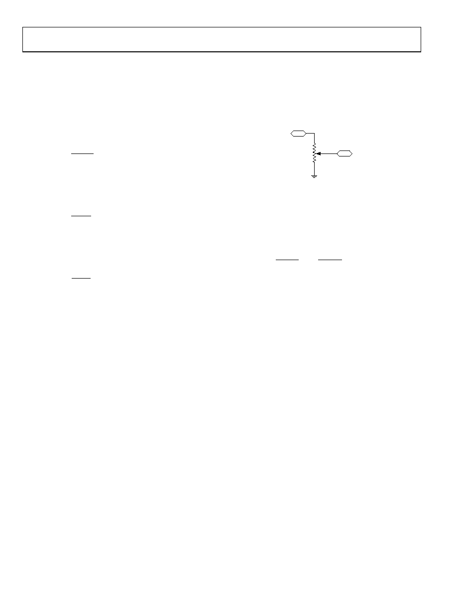
PROGRAMMING THE POTENTIOMETER DIVIDER
Voltage Output Operation
The digital potentiometer easily generates a voltage divider at
W-to-B and W-to-A that is proportional to the input voltage at
GND, which must be positive, current across A-to-B, W-to-A,
and W-to-B can be in either direction.
A
VI
W
B
VO
09654-
045
Figure 44. Potentiometer Mode Configuration
If ignoring the effect of the wiper resistance for simplicity,
connecting Terminal A to 5 V and Terminal B to ground
produces an output voltage at W to B ranging from 0 V to 5 V.
The general equation defining the output voltage at VW with
respect to ground for any valid input voltage applied to
Terminal A and Terminal B, is
B
AB
AW
A
AB
WB
W
V
R
D
R
V
R
D
R
D
V
×
+
×
=
)
(
)
(
)
(
(16)
where:
RWB(D) can be obtained from Equation 1 to Equation 6.
RAW(D) can be obtained from Equation 7 to Equation 14.
Operation of the digital potentiometer in the divider mode
results in a more accurate operation over temperature. Unlike
the rheostat mode, the output voltage is dependent mainly
on the ratio of the internal resistors, RWA and RWB, and not the
absolute values. Therefore, the temperature drift reduces to
5 ppm/°C.
TERMINAL VOLTAGE OPERATING RANGE
ESD diodes for protection. These diodes also set the voltage
boundary of the terminal operating voltages. Positive signals
present on the A, B, or W terminals that exceed VDD are
clamped by the forward-biased diode. There is no polarity
constraint between VA, VW, and VB, but they cannot be higher
than VDD or lower than GND.
A
相关PDF资料 |
PDF描述 |
|---|---|
| H3BBH-5036G | IDC CABLE - HSR50H/AE50G/HSR50H |
| H8MMH-2636M | DIP CABLE - HDM26H/AE26M/HDM26H |
| ESM10DRSN | CONN EDGECARD 20POS DIP .156 SLD |
| VI-B6D-EW | CONVERTER MOD DC/DC 85V 100W |
| HK06033N0S-T | INDUCTOR HIFREQ 3.0+/-.3NH 0201 |
相关代理商/技术参数 |
参数描述 |
|---|---|
| EVAL-AD5116EBZ | 功能描述:BOARD EVAL FOR AD5116 RoHS:是 类别:编程器,开发系统 >> 评估演示板和套件 系列:* 标准包装:1 系列:- 主要目的:电信,线路接口单元(LIU) 嵌入式:- 已用 IC / 零件:IDT82V2081 主要属性:T1/J1/E1 LIU 次要属性:- 已供物品:板,电源,线缆,CD 其它名称:82EBV2081 |
| EVAL-AD5141DBZ | 功能描述:数字电位计开发工具 EVALUATION BOARD I.C. RoHS:否 制造商:Arduino 产品:TinkerKit Rotary Potentiometers 工具用于评估:TinkerKit 电阻:4.7 kOhms 工作电源电压:0 V to 5 V |
| EVAL-AD5142ADBZ | 功能描述:数字电位计开发工具 EVALUATION BOARD I.C. RoHS:否 制造商:Arduino 产品:TinkerKit Rotary Potentiometers 工具用于评估:TinkerKit 电阻:4.7 kOhms 工作电源电压:0 V to 5 V |
| EVAL-AD5142DBZ | 功能描述:数字电位计开发工具 EVALUATION BOARD I.C. RoHS:否 制造商:Arduino 产品:TinkerKit Rotary Potentiometers 工具用于评估:TinkerKit 电阻:4.7 kOhms 工作电源电压:0 V to 5 V |
| EVAL-AD5143DBZ | 功能描述:数字电位计开发工具 EVALUATION BOARD I.C. RoHS:否 制造商:Arduino 产品:TinkerKit Rotary Potentiometers 工具用于评估:TinkerKit 电阻:4.7 kOhms 工作电源电压:0 V to 5 V |
发布紧急采购,3分钟左右您将得到回复。