- 您现在的位置:买卖IC网 > PDF目录68993 > FA5515P (FUJI ELECTRIC CO LTD) 1.5 A SWITCHING CONTROLLER, 500 kHz SWITCHING FREQ-MAX, PDIP8 PDF资料下载
参数资料
| 型号: | FA5515P |
| 厂商: | FUJI ELECTRIC CO LTD |
| 元件分类: | 稳压器 |
| 英文描述: | 1.5 A SWITCHING CONTROLLER, 500 kHz SWITCHING FREQ-MAX, PDIP8 |
| 封装: | DIP-8 |
| 文件页数: | 13/22页 |
| 文件大小: | 260K |
| 代理商: | FA5515P |
FA551X
20
15. Loss calculation
IC loss must be confirmed to use the IC within the ratings.
Since it is hard to directly measure IC loss, some examples of
calculating approximate IC loss are given below.
15.1 Calculation example 1
Suppose the supply voltage is Vcc, IC current consumption is
lccop, the total gate charge of the power MOSFET is Qg, and
the switching frequency is fSW. Total IC loss Pd can be
calculated by:
Pd
VCC
(ICCOP + Qg
fsw)
This expression calculates an approximate value of Pd, which is
normally a little larger than the actual loss. Since various
conditions such as temperature characteristics apply,
thoroughly verify the appropriateness of the calculation under
all applicable conditions.
Example:
When Vcc=18V, lccop=2.5mA (max.) is obtained from the
specifications. Suppose Qg=80nC and fsw=100kHz.
Pd
18V
(2.5mA + 80nC
100kHz)
189mW
15.2 Calculation example 2
The IC loss consists of the loss caused by operation of the
control circuit and the loss caused at the output circuit to drive
the power MOSFET.
15.2.1 Loss at the control circuit
The loss caused by operation of the IC control circuit is
calculated by the supply voltage and IC current consumption.
When the supply voltage is Vcc and IC current consumption is
lccop, loss Pop at the control circuit is:
Pop = VCC
ICCOP
Example:
When Vcc=18, lccop=1.9mA (typ) is obtained from the
specifications. The typical IC loss is given by:
Pop = 18V
1.5mA = 27mW
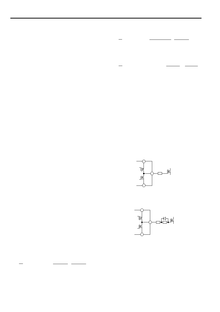
15.2.2 Loss at the output circuit
The output circuit of the IC is a MOSFET push-pull circuit.
When the ON resistances of MOSFETs making up the output
circuit are Ron and Roff, the resistances can be determined as
shown below based on Vcc=18V and Tj = 25C obtained from
the output characteristics shown in the specifications:
Ron = 15
(typ), Roff=7 (typ)
When the total gate charge of the power MOSFET is Qg, the
switching frequency is fSW, the supply voltage is Vcc, and gate
resistance is Rg, the loss caused at the IC output circuit is given
by:
OUT
VCC
GND
Qoff
Rg
Qon
5
6
4
Fig. 35
Output Circuit (1)
OUT
VCC
GND
Qoff
Rg1
Qon
Rg2
6
5
4
Fig. 36
Output Circuit (2)
()
Pdr =
1
18V
80nC
100kHz
15
+
7
210
+15
10
+7
=72.8mW
........................................ (12)
........................................................... (13)
()
Pdr =
1
VCC Qg fsw
Ron
+
Roff
2
Rg + Ron
Rg + Roff
...... (14)
()
Pdr =
1
VCC Qg fsw
Ron
+
Roff
2
Rg1+Rg2+Ron
Rg1+Roff
.... (15)
When gate resistance differs between ON and OFF as shown
in Figure 36, the loss is given by:
Example:
When Vcc=18V, Qg=80nC, fsw=100kHz, and Rg=10
, the
typical IC loss is given by:
15.2.3 Total loss
The total loss (Pd) of the IC is the sum of the control circuit loss
(Pop) and the output circuit loss (Pdr) calculated previously:
Pd = Pop + Pdr
Example:
The standard IC loss under the conditions used in (1) and (2)
above are:
Pd = Pop + Pdr = 27mW + 72.8mW = 99.8mW
.................................................................. (16)
相关PDF资料 |
PDF描述 |
|---|---|
| FA5514N | 1.5 A SWITCHING CONTROLLER, 500 kHz SWITCHING FREQ-MAX, PDSO8 |
| FA5515N | 1.5 A SWITCHING CONTROLLER, 500 kHz SWITCHING FREQ-MAX, PDSO8 |
| FA5510N | 1.5 A SWITCHING CONTROLLER, 500 kHz SWITCHING FREQ-MAX, PDSO8 |
| FA5511P | 1.5 A SWITCHING CONTROLLER, 500 kHz SWITCHING FREQ-MAX, PDIP8 |
| FA5514P | 1.5 A SWITCHING CONTROLLER, 500 kHz SWITCHING FREQ-MAX, PDIP8 |
相关代理商/技术参数 |
参数描述 |
|---|---|
| FA5515P-D1 | 制造商:Fuji Electric 功能描述: |
| FA551X | 制造商:未知厂家 制造商全称:未知厂家 功能描述:CMOS IC For Switching Power Supply Control |
| FA5526 | 制造商:FUJI 制造商全称:Fuji Electric 功能描述:Fuji Switching Power Control IC |
| FA5527 | 制造商:FUJI 制造商全称:Fuji Electric 功能描述:Fuji Switching Power Control IC |
| FA5527P-A2 | 制造商:Fuji Electric 功能描述: |
发布紧急采购,3分钟左右您将得到回复。