- 您现在的位置:买卖IC网 > PDF目录383107 > ILD223 (SIEMENS A G) DUAL PHOTODARLINGTON SMALL OUTLINE SURFACE MOUNT OPTOCOUPLER PDF资料下载
参数资料
| 型号: | ILD223 |
| 厂商: | SIEMENS A G |
| 元件分类: | 光电耦合器 |
| 英文描述: | DUAL PHOTODARLINGTON SMALL OUTLINE SURFACE MOUNT OPTOCOUPLER |
| 中文描述: | 2 CHANNEL DARLINGTON OUTPUT OPTOCOUPLER |
| 封装: | SO-8 |
| 文件页数: | 1/2页 |
| 文件大小: | 59K |
| 代理商: | ILD223 |
5–1
FEATURES
Two Channel Optocoupler
High Current Transfer Ratio at I
500% Min.
Isolation Test Voltage, 2500 VRMS
Electrical Specifications Similar to Standard
6-pin Coupler
Compatible with Dual Wave, Vapor Phase and
IR Reflow Soldering
Industry Standard SOIC-8 Surface Mountable
Package
Standard Lead Spacing, .05"
Available in Tape and Reel Option (Conforms
to EIA Standard 481-2)
Underwriters Lab File #E52744
DESCRIPTION
F
=1 mA,
The ILD223 is a high current transfer ratio (CTR)
optocoupler. It has a Gallium Arsenide infrared LED
emitter and a silicon NPN photodarlington transis-
tor detector.
This device has CTRs tested at an LED current of
1 mA. This low drive current permits easy interfac-
ing from CMOS to LSTTL or TTL.
The ILD223 is constructed in a standard SOIC-8
foot print which makes it ideally suited for high den-
sity applications. In addition to eliminating through-
holes requirements, this package conforms to stan-
dards for surface mounted devices.
Maximum Ratings
(Each Channel)
Emitter
Peak Reverse Voltage .....................................6.0 V
Peak Pulsed Current (1
μ
s, 300 pps).................3 A
Continuous Forward Current per Channel ....30 mA
Power Dissipation at 25
°
C............................45 mW
Derate Linearly from 25
°
C ......................0.4 mW/
Detector
Collector-Emitter Breakdown Voltage...............30 V
Emitter-Collector Breakdown Voltage.................5 V
Power Dissipation per Channel................... 75 mW
Derate Linearly from 25
°
C ......................3.1 mW/
Package
Total Package Dissipation at 25
(2 LEDs + 2 Detectors, 2 Channels).......240 mW
Derate Linearly from 25
°
C .........................2 mW/
Storage Temperature ...................–55
Operating Temperature............... –55
Soldering Time at 260
°
C .............................10 sec.
°
C
°
C
°
C Ambient
°
°
°
C
C
C
°
°
C to +150
C to +100
Characteristics
(T
A
=25
°
C)
Symbol
Min.
Typ.
Max.
Unit
Condition
Emitter
Forward Voltage
V
F
1.3
V
I
F
=1 mA
Reverse Current
I
R
0.1
100
μ
A
V
R
=6.0 V
Capacitance
C
O
25
pF
V
F=1 MHz
=0 V,
Detector
Breakdown
Voltage
Collector-Emitter
Emitter-Collector
BV
BV
CEO
ECO
30
5
V
V
I
I
C
E
=10 mA
=10 mA
Current,
Collector-Emitter
I
CEO
50
nA
V
I
F
CE
=5 V,
Capacitance,
Collector-Emitter
C
CE
3.4
pF
V
CE
=5 V
Package
DC Current
Transfer Ratio
CTR
DC
500
%
I
V
F
=1 mA,
CE
=5 V
Saturation
Voltage,
Collector-Emitter
V
CEsat
1
V
I
I
F
CE
=1 mA,
=0.5 mA
Capacitance,
Input to Output
C
IO
0.5
pF
Resistance,
Input to Output
R
IO
100
G
Turn-On Time
t
ON
15
μ
s
V
R
I
F
CC
L
=100
=5 mA
=10 V
Turn-Off Time
t
OFF
30
μ
s
Isolation Test
Voltage
V
IO
(t=1 min.)
2500 VAC
RMS
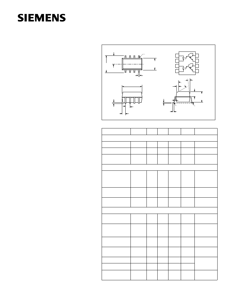
Dimensions in inches (mm)
1
2
3
4
Anode
Cathode
Anode
Cathode
8
7
6
5
Collector
Emitter
Collector
Emitter
40
°
.240
(6.10)
.154
±
.005
(3.91
±
.13)
.050 (1.27) Typ.
.016 (.41)
.192
±
.005
(4.88
±
.13)
.004 (.10)
.008 (.20)
Lead
Coplanarity
±
.001 (.04)
Max.
.015
±
.002
(.38
±
.05)
.008 (.20)
7
°
.058
±
.005
(1.49
±
.13)
.125
±
.005
(3.18
±
.13)
Pin 1
.120
±
.005
(3.05
±
.13)
CL
.040 (1.02)
5
°
Max.
R.010
(.25) Max.
.020
±
.004
(.15
±
.10)
2 Plcs.
ILD223
DUAL PHOTODARLINGTON
SMALL OUTLINE
SURFACE MOUNT OPTOCOUPLER
相关PDF资料 |
PDF描述 |
|---|---|
| ILD66 | PHOTODARLINGTON OPTOCOUPLER |
| IL66 | PHOTODARLINGTON OPTOCOUPLER |
| ILD766 | BIDIRECTIONAL INPUT DARLINGTON OPTOCOUPLERS |
| IL766 | SMT Rotary Dip |
| ILH100 | HERMETIC PHOTOTRANSISTOR OPTOCOUPLER |
相关代理商/技术参数 |
参数描述 |
|---|---|
| ILD223T | 功能描述:晶体管输出光电耦合器 Photodarlington Out Dual CTR >500% RoHS:否 制造商:Vishay Semiconductors 输入类型:DC 最大集电极/发射极电压:70 V 最大集电极/发射极饱和电压:0.4 V 绝缘电压:5300 Vrms 电流传递比:100 % to 200 % 最大正向二极管电压:1.65 V 最大输入二极管电流:60 mA 最大集电极电流:100 mA 最大功率耗散:100 mW 最大工作温度:+ 110 C 最小工作温度:- 55 C 封装 / 箱体:DIP-4 封装:Bulk |
| ILD223T | 制造商:Vishay Semiconductors 功能描述:Optocoupler |
| ILD223T_07 | 制造商:VISHAY 制造商全称:Vishay Siliconix 功能描述:Optocoupler, Photodarlington Output, Dual Channel, SOIC-8 Package |
| ILD24-ACC/N | 制造商:Newport Electronics Inc 功能描述:CURRENT METER, No. of Digits / Alpha:4, Meter Function:AC Amps / AC Milliamps, Meter Range:0mA to 10mA / 0mA to 100mA / 0A to 1A / 0mA to 5A, Digit Height:57.2mm, Panel Cutout Height:116.8mm, Panel Cutout Width:279.4mm , RoHS Compliant: NA |
| ILD24-ACV/N,FS | 制造商:Newport Electronics Inc 功能描述:VOLTAGE METER, No. of Digits / Alpha:4, Meter Function:AC Millivolts / AC Volts, |
发布紧急采购,3分钟左右您将得到回复。