- 您现在的位置:买卖IC网 > PDF目录20491 > IR2114SS (International Rectifier)IC DRIVER HALF-BRIDGE 24-SSOP PDF资料下载
参数资料
| 型号: | IR2114SS |
| 厂商: | International Rectifier |
| 文件页数: | 14/33页 |
| 文件大小: | 0K |
| 描述: | IC DRIVER HALF-BRIDGE 24-SSOP |
| 标准包装: | 55 |
| 配置: | 半桥 |
| 输入类型: | 非反相 |
| 延迟时间: | 440ns |
| 电流 - 峰: | 2A |
| 配置数: | 1 |
| 输出数: | 2 |
| 高端电压 - 最大(自引导启动): | 600V |
| 电源电压: | 11.5 V ~ 20 V |
| 工作温度: | -40°C ~ 125°C |
| 安装类型: | 表面贴装 |
| 封装/外壳: | 24-SSOP(0.209",5.30mm 宽) |
| 供应商设备封装: | 24-SSOP |
| 包装: | 管件 |
第1页第2页第3页第4页第5页第6页第7页第8页第9页第10页第11页第12页第13页当前第14页第15页第16页第17页第18页第19页第20页第21页第22页第23页第24页第25页第26页第27页第28页第29页第30页第31页第32页第33页
�� �
�
�IR2114/IR2214SSPbF�
�of� current� flowing� in� the� circuit� is� determined� by� the�
�internal� pull� up� resistor� value.�
�In� the� high� side� circuit,� the� desaturation� biasing� current�
�may� become� relevant� for� dimensioning� the� bootstrap�
�capacitor� (see� Fig.� 19).� In� fact,� a� pull� up� resistor� with� a�
�low� resistance� may� result� in� a� high� current� the�
�significantly� discharges� the� bootstrap� capacitor.� For� that�
�reason,� the� internal� pull� up� resistor� typical� value� is� of� the�
�order� of� 100� k� .�
�While� the� impedance� of� the� DSH/DSL� pins� is� very� low�
�when� the� transistor� is� on� (low� impedance� path� through�
�1.�
�2.�
�3.�
�Desaturation� detection� event:� the� FAULT/SD�
�pin� is� latched� low� when� SSD� is� over,� and� only� a�
�FLT_CLR� signal� can� reset� it;�
�Undervoltage� on� V� CC� :� the� FAULT/SD� pin� is�
�forced� low� and� held� until� the� undervoltage� is�
�active. Thi� s� event� is� not� latched;�
�FAULT/SD� is� externally� driven� low� either� from�
�the� controller� or� from� another� IR2114/IR2214�
�device.� This� event� is� not� latched;� therefore� the�
�FLT_CLR� cannot� disable� it.� Only� when�
�FAULT/SD� becomes� high� the� device� returns� to�
�its� normal� operating� mode.�
�the� external� diode� down� to� the� power� transistor),� the�
�impedance� is� only� controlled� by� the� pull� up� resistor� when�
�the� transistor� is� off.� In� that� case,� relevant� dV/dt�
�generated� at� VS� node� might� push� the� DSH/DSL� pins�
�outside� the� recommended� operating� conditions.�
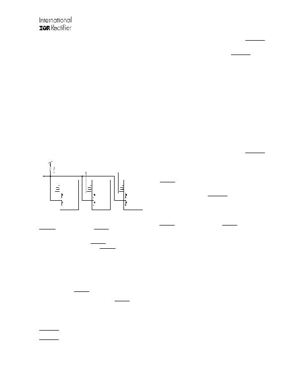
�1.4.4� Fault� Management� in� Multi-Phase� Systems�
�In� a� system� with� two� or� more� gate� drivers� the�
�IR2114/IR2214� devices� must� be� connected� as� shown� in�
�Fig.� 15.�
�FAULT�
�1.4.5� Fault� Management� at� Start-up�
�When� the� bootstrap� supply� topology� is� used� for�
�supplying� the� floating� high� side� and� the� recommended�
�power� supply� start-up� sequence� is� followed,� FLT_CLR�
�pin� must� be� kept� active� to� prevent� spurious� diagnostic�
�signals� being� generated.�
�In� the� event� of� power� inverter� failure� already� present� or�
�occurring� during� start-up� (phase� and/or� rail� supply� short-�
�circuit,� overload� conditions� induced� by� the� load,� etc.),�
�keeping� the� FLT_CLR� pin� active� will� also� p� revent the�
�real� fault� condition� to� be� detected� with� the� FAULT/SD�
�pin.� In� such� a� condition� a� large� current� increase� in� the�
�IGBT� will� desaturate� the� transistor,� allowing� the� gate�
�driver� to� detect� and� turn-off� the� desaturated� transistor�
�with� the� integrated� soft� shutdown� (SSD)� protection.�
�As with� a� normal� SSD� sequence,� during� SSD� the�
�VCC�
�LIN�
�VB�
�HOP�
�VCC�
�LIN�
�VB�
�HOP�
�VCC�
�LIN�
�VB�
�HOP�
�SY_FLT� output� pin� (active� low,� see� Fig.� 14)� will� report�
�SY_FLT�
�HIN�
�FLT_CLR�
�HON�
�SSH�
�DSH�
�VS�
�SY_FLT�
�HIN�
�FLT_CLR�
�HON�
�SSH�
�DSH�
�VS�
�SY_FLT�
�HIN�
�FLT_CLR�
�HON�
�SSH�
�DSH�
�VS�
�the� gate� driver� status.� But� now,� being� the� FLT_CLR� pin�
�already� active,� the� gate� driver� will� not� generate� a� FAULT�
�FAULT/SD�
�LOP�
�LON�
�FAULT/SD�
�LOP�
�LON�
�FAULT/SD�
�LOP�
�LON�
�signal� by� activating� the� FAULT/SD� pin� and� it� will� not�
�SSL�
�DSL�
�SSL�
�DSL�
�SSL�
�DSL�
�enter� hard� shutdown.�
�VSS�
�COM�
�VSS�
�COM�
�VSS�
�COM�
�To� prevent� the� driver� to� resume� charging� the� bootstrap�
�phase� U�
�phase� V�
�phase� W�
�capacitor,� therefore� re-establishing� the� condition� that� will�
�Figure� 15:� IR2214� used� in� a� 3� phase� application�
�SY_FLT:� The� bi-directional� SY_FLT� pins� communicate�
�each� other� through� a� local� network.� The� logic� signal� is�
�active� low.� The� device� that� detects� the� IGBT�
�desaturation� activates� the� SY_FLT,� which� is� then� read�
�by� the� other� gate� drivers.� When� SY_FLT� is� active� all� the�
�drivers� hold� their� output� state� regardless� of� the� input�
�signals� (H� IN� ,� L� IN� )� they� receive� from� the� controller� (freeze�
�state).� This� feature� is� particularly� important� in� phase-to-�
�phase� short� circuit� where� two� IGBTs� are� involved;� in�
�fact,� while� one� is� softly� shutting-down,� the� other� must� be�
�prevented� from� hard� shutdown� to� avoid� exiting� SSD.� In�
�the� freeze� state,� the� frozen� drivers� are� not� completely�
�inactive� because� desaturation� detection� still� takes� the�
�highest� priority.� SY_FLT� communication� has� been�
�designed� for� creating� a� local� network� between� the�
�drivers.� There� is� no� need� to� wire� SY_FLT� to� the�
�controller.�
�determine� again� the� occurrence� of� the� large� current�
�increas� e� in� the� IGBT,� it� is� recommended� to� monitor� the�
�SY_FLT� output� pin.� Should� the� SY_FLT� output� pin� go�
�low� during� the� start-up� sequence,� the� controller� must�
�interpret� a� power� inverter� failure� is� present,� and� stop� the�
�start-up� sequence.�
�1.6� Output� Stage�
�The� structure� is� shown� in� Fig.� 13� and� consists� of� two�
�turn� on� stages� and� one� turn� off� stage.� When� the� driver�
�turns� on� the� IGBT� (see� Fig.� 8),� a� first� stage� is� activated�
�while� an� additional� stage� is� maintained� in� the� active� state�
�for� a� limited� time� (t� on1� ).� This� feature� boosts� the� total�
�driving� capability� in� order� to� accommodate� both� a� fast�
�gate� charge� to� the� plateau� voltage� and� dV/dt� control� in�
�switching.�
�At� turn� off,� a� single� n-channel� sinks� up� to� 3� A� (I� O-� )� and�
�offers� a� low� impedance� path� to� prevent� the� self-turn� on�
�due� to� the� parasitic� Miller� capacitance� in� the� power�
�FAULT/SD:�
�The� bi-directional� FAULT/SD� pins�
�switch.�
�communicate� with� each� other� and� with� the� system�
�controller.� The� logic� signal� is� active� low.� When� low,� the�
�FAULT/SD� signal� commands� the� outputs� to� go� off� by�
�hard� shutdown.� There� are� three� events� that� can� force�
�FAULT/SD� low:�
�www.irf.com�
�14�
�1.7� Timing� and� Logic� State� Diagrams� Description�
�The� following� figures� show� the� input/output� logic�
�diagram.� Figure� 17� shows� the� SY_FLT� and� FAULT/SD�
�signals� as� outputs,� whereas� Fig.� 18� shows� them� as�
�inputs.�
�?� 2009� International� Rectifier�
�相关PDF资料 |
PDF描述 |
|---|---|
| M7OOK-2510R | D-SUB CABLE MFL25K/MC26M/MFL25K |
| 395-056-527-804 | CARD EDGE 56POS DL .100X.200 BLK |
| IX6R11S3 | HALF BRIDGE DRIVER 16-SOIC |
| M7SSK-3710J | D-SUB CABLE MFM37K/MC37G/MFM37K |
| 395-056-527-802 | CARD EDGE 56POS DL .100X.200 BLK |
相关代理商/技术参数 |
参数描述 |
|---|---|
| IR2114SSPBF | 功能描述:功率驱动器IC 600V HALF BRDG DRVR IC RoHS:否 制造商:Micrel 产品:MOSFET Gate Drivers 类型:Low Cost High or Low Side MOSFET Driver 上升时间: 下降时间: 电源电压-最大:30 V 电源电压-最小:2.75 V 电源电流: 最大功率耗散: 最大工作温度:+ 85 C 安装风格:SMD/SMT 封装 / 箱体:SOIC-8 封装:Tube |
| IR2114SSPBF | 制造商:International Rectifier 功能描述:Driver IC |
| IR2114SSTRPBF | 功能描述:功率驱动器IC 600V Hlf Brdg Drvr IC for Pwr Swtch App RoHS:否 制造商:Micrel 产品:MOSFET Gate Drivers 类型:Low Cost High or Low Side MOSFET Driver 上升时间: 下降时间: 电源电压-最大:30 V 电源电压-最小:2.75 V 电源电流: 最大功率耗散: 最大工作温度:+ 85 C 安装风格:SMD/SMT 封装 / 箱体:SOIC-8 封装:Tube |
| IR2117 | 功能描述:IC MOSFET DRIVER SGL-CH 8-DIP RoHS:否 类别:集成电路 (IC) >> PMIC - MOSFET,电桥驱动器 - 外部开关 系列:- 标准包装:50 系列:- 配置:高端 输入类型:非反相 延迟时间:200ns 电流 - 峰:250mA 配置数:1 输出数:1 高端电压 - 最大(自引导启动):600V 电源电压:12 V ~ 20 V 工作温度:-40°C ~ 125°C 安装类型:通孔 封装/外壳:8-DIP(0.300",7.62mm) 供应商设备封装:8-DIP 包装:管件 其它名称:*IR2127 |
| IR2117PBF | 功能描述:功率驱动器IC 1 HI SIDE DRVR NONINVERTING INPUT RoHS:否 制造商:Micrel 产品:MOSFET Gate Drivers 类型:Low Cost High or Low Side MOSFET Driver 上升时间: 下降时间: 电源电压-最大:30 V 电源电压-最小:2.75 V 电源电流: 最大功率耗散: 最大工作温度:+ 85 C 安装风格:SMD/SMT 封装 / 箱体:SOIC-8 封装:Tube |
发布紧急采购,3分钟左右您将得到回复。