- 您现在的位置:买卖IC网 > PDF目录377498 > IR2166 (International Rectifier) RES 560 OHM 1/10W 5% SM PDF资料下载
参数资料
| 型号: | IR2166 |
| 厂商: | International Rectifier |
| 英文描述: | RES 560 OHM 1/10W 5% SM |
| 中文描述: | 功率因数校正 |
| 文件页数: | 20/29页 |
| 文件大小: | 371K |
| 代理商: | IR2166 |
第1页第2页第3页第4页第5页第6页第7页第8页第9页第10页第11页第12页第13页第14页第15页第16页第17页第18页第19页当前第20页第21页第22页第23页第24页第25页第26页第27页第28页第29页
IR2166
20
www.irf.com
4
3
3uA
5
2
CPH
CT
RPH
RT
11
12
COM
LO
M2
R
CS
OSC
16
HO
M1
15
VS
C
CPH
C
T
Half-
Bridge
Output
I
LOAD
(+)
V
BUS
(-)
Load
Return
Half-
Bridge
Driver
IR2166
1.3V
S1
S4
Comp 4
10
13
VCC
CS
R1
C
CS
S3
Fault
Logic
V
BUS
R
T
R
PH
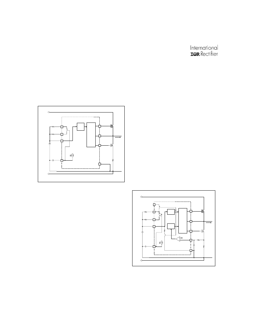
oscillate at the preheat frequency with 50% duty
cycle and with a dead-time which is set by the
value of the external timing capacitor, CT, and
internal deadtime resistor, RDT. Pin CPH is
disconnected from COM and an internal 3
μ
A
current source (Figure 3)
Figure 3, Preheat circuitry.
charges the external preheat timing capacitor
on CPH linearly. The over-current protection on
pin CS is disabled during preheat. The preheat
frequency is determined by the parallel
combination of resistors RT and RPH, together
with timing capacitor CT. CT charges and
discharges between 1/3 and 3/5 of VCC (see
Timing Diagram, page 9). CT is charged
exponentially through the parallel combination
of RT and RPH connected internally to VCC
through MOSFET S1. The charge time of CT
from 1/3 to 3/5 VCC is the on-time of the
respective output gate driver, HO or LO. Once
CT exceeds 3/5 VCC, MOSFET S1 is turned
off, disconnecting RT and RPH from VCC. CT is
then discharged exponentially through an
internal resistor, RDT, through MOSFET S3 to
COM. The discharge time of CT from 3/5 to 1/3
VCC is the dead-time (both off) of the output
gate drivers, HO and LO. The selected value of
CT together with RDT therefore program the
desired dead-time (see Design Equations, page
26, Equations 1 and 2). Once CT discharges
below 1/3 VCC, MOSFET S3 is turned off,
disconnecting RDT from COM, and MOSFET
S1 is turned on, connecting RT and RPH again
to VCC. The frequency remains at the preheat
frequency until the voltage on pin CPH exceeds
10V and the IC enters Ignition Mode. During the
preheat mode, the over-current protection
together with the fault counter are enabled. The
peak ignition current must not exceed the
maximum allowable current ratings of the output
stage MOSFETs. Should this voltage exceed the
internal threshold of 1.3V, the internal FAULT
Counter begins counting the sequential over-
current faults (See Timing Diagram). If the
number of over-current faults exceed 25, the IC
will enter FAULT mode and gate driver outputs
HO, LO and PFC will be latched low.
Figure 4, Ignition circuitry.
4
3
3uA
5
2
CPH
CT
RPH
RT
11
12
COM
LO
M2
RCS
OSC.
16
HO
M1
15
VS
R
T
C
CPH
Half-
Bridge
Output
I
LOAD
V
BUS
(+)
V
BUS
(-)
Load
Return
Half-
Bridge
Driver
IR2166
S4
R
PH
C
T
相关PDF资料 |
PDF描述 |
|---|---|
| IR2166PBF | PFC & BALLAST CONTROL IC |
| IR2166S | PFC & BALLAST CONTROL IC |
| IR2167 | PFC BALLAST CONTROL IC |
| IR2167S | PFC Ballast Control. Thermal Overload Protection. Brown Out Protection. Programmable Preheat and Frequency. Programmable Deadtime in a 20 Lead SOIC package |
| IR2170 | OVER CURRENT SENSING IC |
相关代理商/技术参数 |
参数描述 |
|---|---|
| IR2166PBF | 功能描述:功率驱动器IC PFC Ballast Cntrl RoHS:否 制造商:Micrel 产品:MOSFET Gate Drivers 类型:Low Cost High or Low Side MOSFET Driver 上升时间: 下降时间: 电源电压-最大:30 V 电源电压-最小:2.75 V 电源电流: 最大功率耗散: 最大工作温度:+ 85 C 安装风格:SMD/SMT 封装 / 箱体:SOIC-8 封装:Tube |
| IR2166PBF | 制造商:International Rectifier 功能描述:Controller IC Output Voltage Max.:25V |
| IR2166S | 功能描述:IC PFC/BALLAST CONTROL 16-SOIC RoHS:否 类别:集成电路 (IC) >> PMIC - 照明,镇流器控制器 系列:- 产品培训模块:Lead (SnPb) Finish for COTS Obsolescence Mitigation Program 标准包装:2,500 系列:- 类型:CCFL 控制器 频率:40 ~ 80 kHz 电流 - 电源:5mA 电流 - 输出:- 电源电压:4.5 V ~ 5.5 V 工作温度:-40°C ~ 85°C 封装/外壳:16-SOIC(0.154",3.90mm 宽) 供应商设备封装:16-SOIC 包装:带卷 (TR) 其它名称:90-3991V+V01 |
| IR2166SPBF | 功能描述:功率驱动器IC PFC BALLAST CTRL IC 600V 15.6V VCC ESD RoHS:否 制造商:Micrel 产品:MOSFET Gate Drivers 类型:Low Cost High or Low Side MOSFET Driver 上升时间: 下降时间: 电源电压-最大:30 V 电源电压-最小:2.75 V 电源电流: 最大功率耗散: 最大工作温度:+ 85 C 安装风格:SMD/SMT 封装 / 箱体:SOIC-8 封装:Tube |
| IR2166STRPBF | 功能描述:功率驱动器IC PFC Ballast Cntrl RoHS:否 制造商:Micrel 产品:MOSFET Gate Drivers 类型:Low Cost High or Low Side MOSFET Driver 上升时间: 下降时间: 电源电压-最大:30 V 电源电压-最小:2.75 V 电源电流: 最大功率耗散: 最大工作温度:+ 85 C 安装风格:SMD/SMT 封装 / 箱体:SOIC-8 封装:Tube |
发布紧急采购,3分钟左右您将得到回复。