- 您现在的位置:买卖IC网 > PDF目录377498 > IR2166 (International Rectifier) RES 560 OHM 1/10W 5% SM PDF资料下载
参数资料
| 型号: | IR2166 |
| 厂商: | International Rectifier |
| 英文描述: | RES 560 OHM 1/10W 5% SM |
| 中文描述: | 功率因数校正 |
| 文件页数: | 24/29页 |
| 文件大小: | 371K |
| 代理商: | IR2166 |
第1页第2页第3页第4页第5页第6页第7页第8页第9页第10页第11页第12页第13页第14页第15页第16页第17页第18页第19页第20页第21页第22页第23页当前第24页第25页第26页第27页第28页第29页
IR2166
24
www.irf.com
RVBUS1
RVBUS
CCOMP
LPFC
MPFC
RPFC
DFPC
CBUS
(+)
(-)
RZX
PFC
Control
VBUS
COMP
PFC
ZX
COM
DCOMP
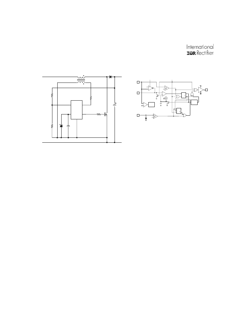
Figure 8:IR2166 simplified PFC control circuit
The VBUS pin is regulated against a fixed
internal 4V reference voltage for regulating the
DC bus voltage (Figure 9). The feedback loop
is performed by an operational transconductance
amplifier (OTA) that sinks or sources a current
to the external capacitor at the COMP pin. The
resulting voltage on the COMP pin sets the
threshold for the charging of the internal timing
capacitor (C1) and therefore programs the on-
time of MPFC. During preheat and ignition
modes of the ballast section, the gain of the
OTA is set to a high level to raise the DC bus
level quickly. When the voltage on the V
BUS
pin
exceeds 3V, the gain is set to a low level to
reduce overshoot. When the voltage on the V
BUS
pin exceeds 4V, the gain is set to a high level
again to minimize the transient on the DC bus
which can occur during ignition. During run
mode, the gain is then decreased to a lower
level necessary for achieving high power factor
and low THD.
Figure 9: IR2166 detailed PFC control circuit
The off-time of MPFC is determined by the time
it takes the LPFC current to discharge to zero.
This zero current level is detected by a
secondary winding on LPFC which is connected
to the ZX pin. A positive-going edge exceeding
the internal 2V threshold signals the beginning
of the off-time. A negative-going edge on the
ZX pin falling below 1.7V will occur when the
LPFC current discharges to zero which signals
the end of the off-time and MPFC is turned on
again (Figure 10). The cycle repeats itself
indefinitely until the PFC section is disabled due
to a fault detected by the ballast section (Fault
Mode), an over-voltage or under-voltage
condition on the DC bus, or, the negative
transition of ZX pin voltage does not occur.
Should the negative edge on the ZX pin not occur,
MPFC will remain off until the watch-dog timer
forces a turn-on of MPFC for an on-time duration
programmed by the voltage on the COMP pin.
The watch-dog pulses occur every 400
μ
s
indefinitely until a correct positive- and negative-
going signal is detected on the ZX pin and normal
PFC operation is resumed.
7
6
1
Q
S
R
Q
2.0V
VBUS
COMP
ZX
7.6V
4.0V
GAIN
OTA1
4.3V
8
PFC
Q
S
R1
R2 Q
COMP3
COMP4
COMP5
RS3
RS4
VCC
Run Mode Signal
Fault Mode Signal
M1
WATCH
DOG
TIMER
M2
C1
3.0V
VCC to
UVLO-
COMP2
相关PDF资料 |
PDF描述 |
|---|---|
| IR2166PBF | PFC & BALLAST CONTROL IC |
| IR2166S | PFC & BALLAST CONTROL IC |
| IR2167 | PFC BALLAST CONTROL IC |
| IR2167S | PFC Ballast Control. Thermal Overload Protection. Brown Out Protection. Programmable Preheat and Frequency. Programmable Deadtime in a 20 Lead SOIC package |
| IR2170 | OVER CURRENT SENSING IC |
相关代理商/技术参数 |
参数描述 |
|---|---|
| IR2166PBF | 功能描述:功率驱动器IC PFC Ballast Cntrl RoHS:否 制造商:Micrel 产品:MOSFET Gate Drivers 类型:Low Cost High or Low Side MOSFET Driver 上升时间: 下降时间: 电源电压-最大:30 V 电源电压-最小:2.75 V 电源电流: 最大功率耗散: 最大工作温度:+ 85 C 安装风格:SMD/SMT 封装 / 箱体:SOIC-8 封装:Tube |
| IR2166PBF | 制造商:International Rectifier 功能描述:Controller IC Output Voltage Max.:25V |
| IR2166S | 功能描述:IC PFC/BALLAST CONTROL 16-SOIC RoHS:否 类别:集成电路 (IC) >> PMIC - 照明,镇流器控制器 系列:- 产品培训模块:Lead (SnPb) Finish for COTS Obsolescence Mitigation Program 标准包装:2,500 系列:- 类型:CCFL 控制器 频率:40 ~ 80 kHz 电流 - 电源:5mA 电流 - 输出:- 电源电压:4.5 V ~ 5.5 V 工作温度:-40°C ~ 85°C 封装/外壳:16-SOIC(0.154",3.90mm 宽) 供应商设备封装:16-SOIC 包装:带卷 (TR) 其它名称:90-3991V+V01 |
| IR2166SPBF | 功能描述:功率驱动器IC PFC BALLAST CTRL IC 600V 15.6V VCC ESD RoHS:否 制造商:Micrel 产品:MOSFET Gate Drivers 类型:Low Cost High or Low Side MOSFET Driver 上升时间: 下降时间: 电源电压-最大:30 V 电源电压-最小:2.75 V 电源电流: 最大功率耗散: 最大工作温度:+ 85 C 安装风格:SMD/SMT 封装 / 箱体:SOIC-8 封装:Tube |
| IR2166STRPBF | 功能描述:功率驱动器IC PFC Ballast Cntrl RoHS:否 制造商:Micrel 产品:MOSFET Gate Drivers 类型:Low Cost High or Low Side MOSFET Driver 上升时间: 下降时间: 电源电压-最大:30 V 电源电压-最小:2.75 V 电源电流: 最大功率耗散: 最大工作温度:+ 85 C 安装风格:SMD/SMT 封装 / 箱体:SOIC-8 封装:Tube |
发布紧急采购,3分钟左右您将得到回复。