- 您现在的位置:买卖IC网 > PDF目录377498 > IR2166 (International Rectifier) RES 560 OHM 1/10W 5% SM PDF资料下载
参数资料
| 型号: | IR2166 |
| 厂商: | International Rectifier |
| 英文描述: | RES 560 OHM 1/10W 5% SM |
| 中文描述: | 功率因数校正 |
| 文件页数: | 25/29页 |
| 文件大小: | 371K |
| 代理商: | IR2166 |
第1页第2页第3页第4页第5页第6页第7页第8页第9页第10页第11页第12页第13页第14页第15页第16页第17页第18页第19页第20页第21页第22页第23页第24页当前第25页第26页第27页第28页第29页
IR2166
www.irf.com
25
0
0
0
I
LPFC
PFC
pin
ZX
pin
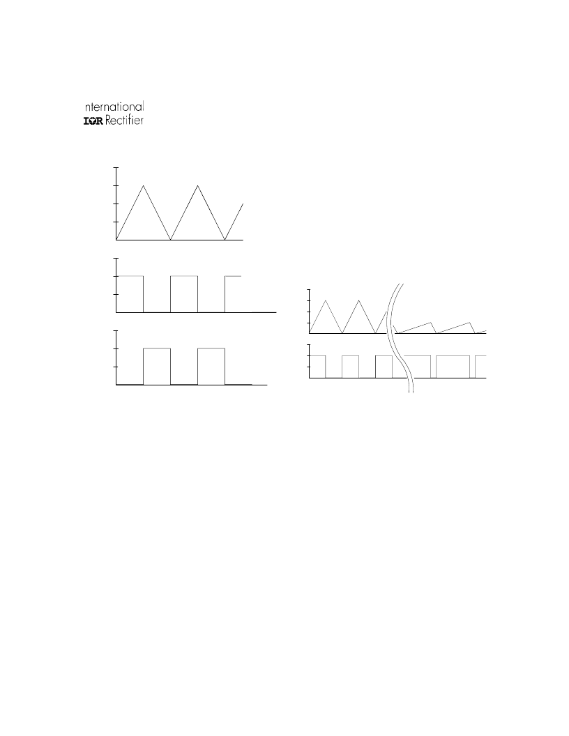
Figure 10: LPFC current, PFC pin and ZX pin timing
diagram.
On-time Modulation
A fixed on-time of MPFC over an entire cycle of
the line input voltage produces a peak inductor
current which naturally follows the sinusoidal
shape of the line input voltage. The smoothed
averaged line input current is in phase with the
line input voltage for high power factor but the
total harmonic distortion (THD), as well as the
individual higher harmonics, of the current can
still be too high. This is mostly due to cross-
over distortion of the line current near the zero-
crossings of the line input voltage. To achieve
low harmonics which are acceptable to
international standard organizations and general
market requirements, an additional on-time
modulation circuit has been added to the PFC
control. This circuit dynamically increases the
on-time of MPFC as the line input voltage nears
the zero-crossings (Figure 11). This causes the
peak LPFC current, and therefore the smoothed
line input current, to increase slightly higher near
the zero-crossings of the line input voltage. This
reduces the amount of cross-over distortion in
the line input current which reduces the THD
and higher harmonics to low levels.
0
0
I
LPFC
PFC
pin
near peak region of
rectified AC line
near zero-crossing region
of rectified AC line
Figure 11: On-time modulation near the zero-crossings.
Over-voltage Protection (OVP)
Should over-voltage occur on the DC bus
causing the VBUS pin to exceed the internal 4.3V
threshold, the PFC output is disabled (set to a
logic 'low'). When the DC bus decreases again
causing the VBUS pin to decrease below the
internal 4V threshold, a watch-dog pulse is forced
on the PFC pin and normal PFC operation is
resumed.
Under-voltage Reset (UVR)
When the line input voltage is decreased,
interrupted or a brown-out condition occurs, the
PFC feedback loop causes the on-time of MPFC
相关PDF资料 |
PDF描述 |
|---|---|
| IR2166PBF | PFC & BALLAST CONTROL IC |
| IR2166S | PFC & BALLAST CONTROL IC |
| IR2167 | PFC BALLAST CONTROL IC |
| IR2167S | PFC Ballast Control. Thermal Overload Protection. Brown Out Protection. Programmable Preheat and Frequency. Programmable Deadtime in a 20 Lead SOIC package |
| IR2170 | OVER CURRENT SENSING IC |
相关代理商/技术参数 |
参数描述 |
|---|---|
| IR2166PBF | 功能描述:功率驱动器IC PFC Ballast Cntrl RoHS:否 制造商:Micrel 产品:MOSFET Gate Drivers 类型:Low Cost High or Low Side MOSFET Driver 上升时间: 下降时间: 电源电压-最大:30 V 电源电压-最小:2.75 V 电源电流: 最大功率耗散: 最大工作温度:+ 85 C 安装风格:SMD/SMT 封装 / 箱体:SOIC-8 封装:Tube |
| IR2166PBF | 制造商:International Rectifier 功能描述:Controller IC Output Voltage Max.:25V |
| IR2166S | 功能描述:IC PFC/BALLAST CONTROL 16-SOIC RoHS:否 类别:集成电路 (IC) >> PMIC - 照明,镇流器控制器 系列:- 产品培训模块:Lead (SnPb) Finish for COTS Obsolescence Mitigation Program 标准包装:2,500 系列:- 类型:CCFL 控制器 频率:40 ~ 80 kHz 电流 - 电源:5mA 电流 - 输出:- 电源电压:4.5 V ~ 5.5 V 工作温度:-40°C ~ 85°C 封装/外壳:16-SOIC(0.154",3.90mm 宽) 供应商设备封装:16-SOIC 包装:带卷 (TR) 其它名称:90-3991V+V01 |
| IR2166SPBF | 功能描述:功率驱动器IC PFC BALLAST CTRL IC 600V 15.6V VCC ESD RoHS:否 制造商:Micrel 产品:MOSFET Gate Drivers 类型:Low Cost High or Low Side MOSFET Driver 上升时间: 下降时间: 电源电压-最大:30 V 电源电压-最小:2.75 V 电源电流: 最大功率耗散: 最大工作温度:+ 85 C 安装风格:SMD/SMT 封装 / 箱体:SOIC-8 封装:Tube |
| IR2166STRPBF | 功能描述:功率驱动器IC PFC Ballast Cntrl RoHS:否 制造商:Micrel 产品:MOSFET Gate Drivers 类型:Low Cost High or Low Side MOSFET Driver 上升时间: 下降时间: 电源电压-最大:30 V 电源电压-最小:2.75 V 电源电流: 最大功率耗散: 最大工作温度:+ 85 C 安装风格:SMD/SMT 封装 / 箱体:SOIC-8 封装:Tube |
发布紧急采购,3分钟左右您将得到回复。