参数资料
| 型号: | ISL1209IU10Z |
| 厂商: | Intersil |
| 文件页数: | 23/24页 |
| 文件大小: | 0K |
| 描述: | IC RTC LP BATT BACK SRAM 10MSOP |
| 标准包装: | 80 |
| 类型: | 时间事件记录器 |
| 特点: | 警报器,闰年,SRAM |
| 存储容量: | 2B |
| 时间格式: | HH:MM:SS(12/24 小时) |
| 数据格式: | YY-MM-DD-dd |
| 接口: | I²C,2 线串口 |
| 电源电压: | 2.7 V ~ 5.5 V |
| 电压 - 电源,电池: | 1.8 V ~ 5.5 V |
| 工作温度: | -40°C ~ 85°C |
| 安装类型: | 表面贴装 |
| 封装/外壳: | 10-TFSOP,10-MSOP(0.118",3.00mm 宽) |
| 供应商设备封装: | 10-MSOP |
| 包装: | 管件 |
| 产品目录页面: | 1245 (CN2011-ZH PDF) |
8
FN6109.4
October 17, 2006
Frequency Output Mode. The pin outputs a clock signal
which is related to the crystal frequency. The frequency
output is user selectable and enabled via the I2C bus. It is
an open drain active low output.
Serial Clock (SCL)
The SCL input is used to clock all serial data into and out of
the device. The input buffer on this pin is always active (not
gated). It is disabled when the backup power supply on the
VBAT pin is activated to minimize power consumption.
Serial Data (SDA)
SDA is a bidirectional pin used to transfer data into and out
of the device. It has an open drain output and may be ORed
with other open drain or open collector outputs. The input
buffer is always active (not gated) in normal mode.
An open drain output requires the use of a pull-up resistor.
The output circuitry controls the fall time of the output signal
with the use of a slope controlled pull-down. The circuit is
designed for 400kHz I2C interface speeds. It is disabled
when the backup power supply on the VBAT pin is activated.
VDD, GND
Chip power supply and ground pins. The device will operate
with a power supply from VDD = 2.7V to 5.5VDC. A 0.1F
capacitor is recommended on the VDD pin to ground.
Functional Description
Power Control Operation
The power control circuit accepts a VDD and a VBAT input.
Many types of batteries can be used with Intersil RTC
products. For example, 3.0V or 3.6V Lithium batteries are
appropriate, and battery sizes are available that can power
the ISL1209 for up to 10 years. Another option is to use a
Super Cap for applications where VDD is interrupted for up
to a month. See the Applications Section for more
information.
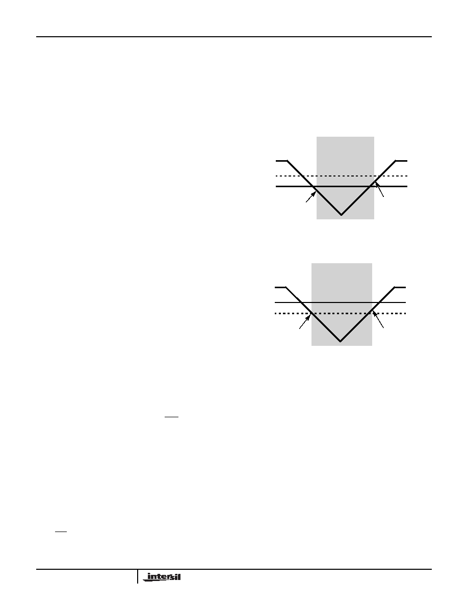
Normal Mode (VDD) to Battery Backup Mode
(VBAT)
To transition from the VDD to VBAT mode, both of the
following conditions must be met:
Condition 1:
VDD < VBAT - VBATHYS
where VBATHYS ≈ 50mV
Condition 2:
VDD < VTRIP
where VTRIP ≈ 2.2V
Battery Backup Mode (VBAT) to Normal Mode
(VDD)
The ISL1209 device will switch from the VBAT to VDD mode
when one of the following conditions occurs:
Condition 1:
VDD > VBAT + VBATHYS
where VBATHYS ≈ 50mV
Condition 2:
VDD > VTRIP + VTRIPHYS
where VTRIPHYS ≈ 30mV
These power control situations are illustrated in Figures 9
and 10.
The I2C bus is deactivated in battery backup mode to provide
lower power. Aside from this, all RTC functions are
operational during battery backup mode. Except for SCL and
SDA, all the inputs and outputs of the ISL1209 are active
during battery backup mode unless disabled via the control
register. The User SRAM is operational in battery backup
mode down to 1.8V.
Power Failure Detection
The ISL1209 provides a Real Time Clock Failure Bit (RTCF)
to detect total power failure. It allows users to determine if
the device has powered up after having lost all power to the
device (both VDD and VBAT).
Low Power Mode
The normal power switching of the ISL1209 is designed to
switch into battery backup mode only if the VDD power is
lost. This will ensure that the device can accept a wide range
of backup voltages from many types of sources while reliably
switching into backup mode. Another mode, called Low
VBAT - VBATHYS
VBAT
VBAT + VBATHYS
BATTERY BACKUP
MODE
VDD
VTRIP
2.2V
1.8V
FIGURE 9. BATTERY SWITCHOVER WHEN VBAT < VTRIP
FIGURE 10. BATTERY SWITCHOVER WHEN VBAT > VTRIP
VBAT
VTRIP + VTRIPHYS
BATTERY BACKUP
MODE
VDD
VTRIP
3.0V
2.2V
VTRIP
ISL1209
相关PDF资料 |
PDF描述 |
|---|---|
| VE-JWV-MZ | CONVERTER MOD DC/DC 5.8V 25W |
| X9313WSZ | IC XDCP 32-TAP 10K 3-WIRE 8-SOIC |
| VE-JW3-MZ | CONVERTER MOD DC/DC 24V 25W |
| VE-JW2-MZ | CONVERTER MOD DC/DC 15V 25W |
| VE-JWT-MZ | CONVERTER MOD DC/DC 6.5V 25W |
相关代理商/技术参数 |
参数描述 |
|---|---|
| ISL1209IU10Z-TK | 功能描述:实时时钟 I2CAL TIME CLK/CLNDR W/EVENT DETCT 10LD RoHS:否 制造商:Microchip Technology 功能:Clock, Calendar. Alarm RTC 总线接口:I2C 日期格式:DW:DM:M:Y 时间格式:HH:MM:SS RTC 存储容量:64 B 电源电压-最大:5.5 V 电源电压-最小:1.8 V 最大工作温度:+ 85 C 最小工作温度: 安装风格:Through Hole 封装 / 箱体:PDIP-8 封装:Tube |
| ISL1218 | 制造商:INTERSIL 制造商全称:Intersil Corporation 功能描述:Low Power RTC with Battery Backed SRAM |
| ISL1218IBZ | 功能描述:实时时钟 REAL TIME CLKRTC IN 8LD RoHS:否 制造商:Microchip Technology 功能:Clock, Calendar. Alarm RTC 总线接口:I2C 日期格式:DW:DM:M:Y 时间格式:HH:MM:SS RTC 存储容量:64 B 电源电压-最大:5.5 V 电源电压-最小:1.8 V 最大工作温度:+ 85 C 最小工作温度: 安装风格:Through Hole 封装 / 箱体:PDIP-8 封装:Tube |
| ISL1218IBZ-T | 功能描述:实时时钟 REAL TIME CLKRTC IN 8LD RoHS:否 制造商:Microchip Technology 功能:Clock, Calendar. Alarm RTC 总线接口:I2C 日期格式:DW:DM:M:Y 时间格式:HH:MM:SS RTC 存储容量:64 B 电源电压-最大:5.5 V 电源电压-最小:1.8 V 最大工作温度:+ 85 C 最小工作温度: 安装风格:Through Hole 封装 / 箱体:PDIP-8 封装:Tube |
| ISL1218IUZ | 功能描述:实时时钟 REAL TIME CLKRTC IN RoHS:否 制造商:Microchip Technology 功能:Clock, Calendar. Alarm RTC 总线接口:I2C 日期格式:DW:DM:M:Y 时间格式:HH:MM:SS RTC 存储容量:64 B 电源电压-最大:5.5 V 电源电压-最小:1.8 V 最大工作温度:+ 85 C 最小工作温度: 安装风格:Through Hole 封装 / 箱体:PDIP-8 封装:Tube |
发布紧急采购,3分钟左右您将得到回复。