- 您现在的位置:买卖IC网 > PDF目录383128 > ISL1219 (Intersil Corporation) Low Power RTC with Battery Backed SRAM and Event Detection(具有电池供电的SRAM和事件检测功能的低功率RTC) PDF资料下载
参数资料
| 型号: | ISL1219 |
| 厂商: | Intersil Corporation |
| 英文描述: | Low Power RTC with Battery Backed SRAM and Event Detection(具有电池供电的SRAM和事件检测功能的低功率RTC) |
| 中文描述: | 低功耗RTC与电池供电的SRAM和事件检测(具有电池供电的SRAM的和事件检测功能的低功率实时时钟) |
| 文件页数: | 9/25页 |
| 文件大小: | 373K |
| 代理商: | ISL1219 |
9
FN6314.1
August 14, 2006
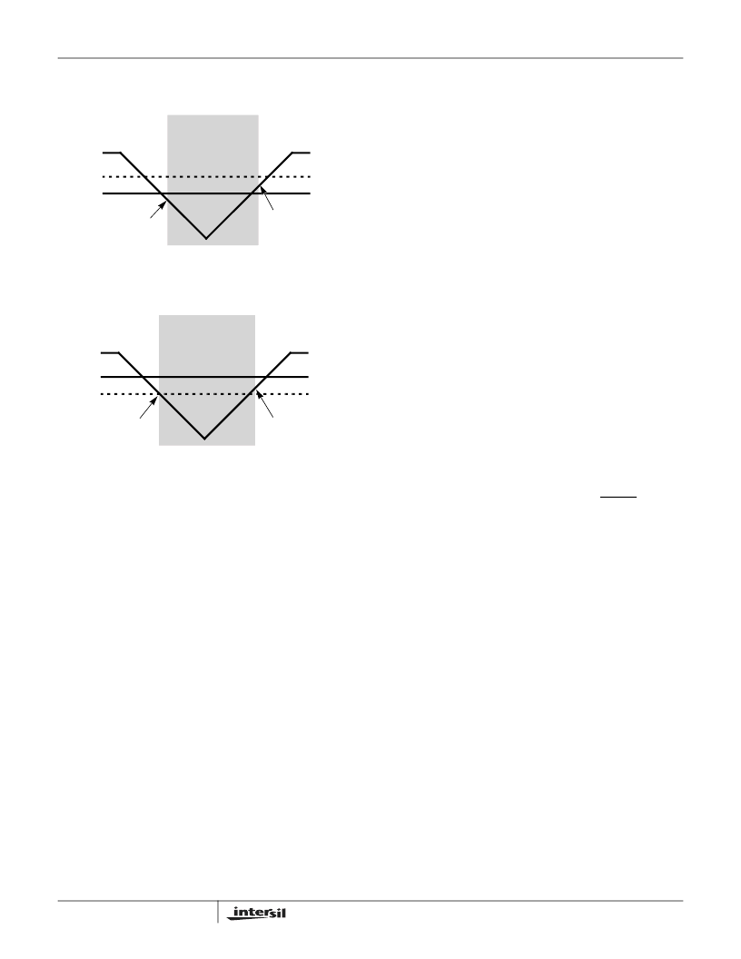
These power control situations are illustrated in Figures 11
and 12.
The I
2
C bus is deactivated in battery backup mode to provide
lower power. Aside from this, all RTC functions are
operational during battery backup mode. Except for SCL and
SDA, all the inputs and outputs of the ISL1219 are active
during battery backup mode unless disabled via the control
register. The User SRAM is operational in battery backup
mode down to 1.8V.
Power Failure Detection
The ISL1219 provides a Real Time Clock Failure Bit (RTCF)
to detect total power failure. It allows users to determine if
the device has powered up after having lost all power to the
device (both V
DD
and V
BAT
).
Low Power Mode
The normal power switching of the ISL1219 is designed to
switch into battery backup mode only if the V
DD
power is
lost. This will ensure that the device can accept a wide range
of backup voltages from many types of sources while reliably
switching into backup mode. Another mode, called Low
Power Mode, is available to allow direct switching from V
DD
to V
BAT
without requiring V
DD
to drop below V
TRIP
. Since
the additional monitoring of V
DD
vs. V
TRIP
is no longer
needed, that circuitry is shut down and less power is used
while operating from V
DD
. Power savings are typically
600nA at V
DD
= 5V. Low Power Mode is activated via the
LPMODE bit in the control and status registers.
Low Power Mode is useful in systems where V
DD
is normally
higher than V
BAT
at all times. The device will switch from
V
DD
to V
BAT
when V
DD
drops below V
BAT
, with about 50mV
of hysteresis to prevent any switchback of V
DD
after
switchover. In a system with a V
DD
= 5V and backup lithium
battery of V
BAT
= 3V, Low Power Mode can be used.
However, it is not recommended to use Low Power Mode in
a system with V
DD
= 3.3V ±10%, V
BAT
≥
3.0V, and when
there is a finite I-R voltage drop in the V
DD
line.
InterSeal Battery Saver
The ISL1219 has the InterSeal Battery Saver which
prevents initial battery current drain before it is first used. For
example, battery-backed RTCs are commonly packaged on
a board with a battery connected. In order to preserve
battery life, the ISL1219 will not draw any power from the
battery source until after the device is first powered up from
the V
DD
source. Thereafter, the device will switchover to
battery backup mode whenever V
DD
power is lost.
Event/Tamper Monitor and Detection
The ISL1219 provides an event detection,
time stamp and
alarm function to be used in a wide variety of applications
ranging from security, warranty monitoring, data collection
and recording.
The tamper detect input pin, EVIN, can be used as a event
or tamper detection input of an external switch (mechanical
or electronic). When the EVIN pin is a valid HIGH, the
ISL1219 sets the EVT bit in the status register and, can
optionally: 1) Issue an Event output signal (EVDET pin) and
store time stamp information in on board SRAM (second,
minute, hour, date, month and year), 2) At the time event
occurred, stop the RTC registers from advancing.
To allow for flexibility of external switches used at the EVIN
pin, the internal pull-up (~1μA in full on mode) can be
disabled/enabled. This will allow more flexibility depending
on the capacitive and resistive loading at the EVIN pin.
A noise filter option is also provided for the event monitor
circuit. The EVIN pin has a time based filter where the EVIN
signal must be stable for a period of time to trigger a valid
detection. The time hysteresis filter can vary from 0, 3.9ms,
15.2ms or 31.25ms.
For low power applications the event monitor can be
sampled at a user selectable rate. The EVIN pin can be
always ON or periodically sampled with a frequency of 1/4, 1
or 2Hz.
V
BAT
- V
BATHYS
V
BAT
V
BAT
+ V
BATHYS
BATTERY BACKUP
MODE
V
DD
V
TRIP
2.2V
1.8V
FIGURE 11. BATTERY SWITCHOVER WHEN V
BAT
< V
TRIP
FIGURE 12. BATTERY SWITCHOVER WHEN V
BAT
> V
TRIP
V
TRIP
V
BAT
V
TRIP
+ V
TRIPHYS
BATTERY BACKUP
MODE
V
DD
V
TRIP
3.0V
2.2V
ISL1219
相关PDF资料 |
PDF描述 |
|---|---|
| ISL1220 | Low Power RTC with 8 Bytes of Battery Backed SRAM and Separate FOUT(具有电池供电的8位SRAM和独立输出的低功率RTC) |
| ISL1221 | Low Power RTC with Battery Backed SRAM and Event Detection(具有电池供电的SRAM和事件检测功能的低功率RTC) |
| ISL21009 | High Voltage Input Precision, Low Noise FGA Voltage References(高电压输入精度,低噪声FGA电压基准) |
| ISL21400 | Programmable Temperature Slope Voltage Reference(可编程温度斜率电压基准) |
| ISL22316 | Low Noise, Low Power I2C Bus, 128 Taps(低噪声,低功率,I2C总线, 128抽头电位器) |
相关代理商/技术参数 |
参数描述 |
|---|---|
| ISL1219IUZ | 功能描述:实时时钟 REAL TIME CLKRTC IN RoHS:否 制造商:Microchip Technology 功能:Clock, Calendar. Alarm RTC 总线接口:I2C 日期格式:DW:DM:M:Y 时间格式:HH:MM:SS RTC 存储容量:64 B 电源电压-最大:5.5 V 电源电压-最小:1.8 V 最大工作温度:+ 85 C 最小工作温度: 安装风格:Through Hole 封装 / 箱体:PDIP-8 封装:Tube |
| ISL1219IUZ-T | 功能描述:实时时钟 REAL TIME CLKRTC IN RoHS:否 制造商:Microchip Technology 功能:Clock, Calendar. Alarm RTC 总线接口:I2C 日期格式:DW:DM:M:Y 时间格式:HH:MM:SS RTC 存储容量:64 B 电源电压-最大:5.5 V 电源电压-最小:1.8 V 最大工作温度:+ 85 C 最小工作温度: 安装风格:Through Hole 封装 / 箱体:PDIP-8 封装:Tube |
| ISL1220 | 制造商:INTERSIL 制造商全称:Intersil Corporation 功能描述:I2C㈢ Real Time Clock/Calendar with Frequency Output |
| ISL1220IUZ | 功能描述:实时时钟 REAL TIME CLKRTC IN RoHS:否 制造商:Microchip Technology 功能:Clock, Calendar. Alarm RTC 总线接口:I2C 日期格式:DW:DM:M:Y 时间格式:HH:MM:SS RTC 存储容量:64 B 电源电压-最大:5.5 V 电源电压-最小:1.8 V 最大工作温度:+ 85 C 最小工作温度: 安装风格:Through Hole 封装 / 箱体:PDIP-8 封装:Tube |
| ISL1220IUZ-T | 功能描述:实时时钟 REAL TIME CLKRTC IN RoHS:否 制造商:Microchip Technology 功能:Clock, Calendar. Alarm RTC 总线接口:I2C 日期格式:DW:DM:M:Y 时间格式:HH:MM:SS RTC 存储容量:64 B 电源电压-最大:5.5 V 电源电压-最小:1.8 V 最大工作温度:+ 85 C 最小工作温度: 安装风格:Through Hole 封装 / 箱体:PDIP-8 封装:Tube |
发布紧急采购,3分钟左右您将得到回复。