参数资料
| 型号: | ISL62881HRTZ |
| 厂商: | Intersil |
| 文件页数: | 23/35页 |
| 文件大小: | 0K |
| 描述: | IC REG PWM SGL PHASE 28TQFN |
| 标准包装: | 75 |
| 应用: | 控制器,Intel IMVP-6.5? |
| 输入电压: | 5 V ~ 25 V |
| 输出数: | 1 |
| 输出电压: | 0.013 V ~ 1.5 V |
| 工作温度: | -10°C ~ 100°C |
| 安装类型: | 表面贴装 |
| 封装/外壳: | 28-WFQFN 裸露焊盘 |
| 供应商设备封装: | 28-TQFN-EP(4x4) |
| 包装: | 管件 |
第1页第2页第3页第4页第5页第6页第7页第8页第9页第10页第11页第12页第13页第14页第15页第16页第17页第18页第19页第20页第21页第22页当前第23页第24页第25页第26页第27页第28页第29页第30页第31页第32页第33页第34页第35页
�� �
�
�ISL62881,� ISL62881B�
�?�
�------------------------------� ?�
�dV� fb�
�� C� vid� ?�
�I� vid� (� t� )� =� C� vid� ×� ------------� ×� ?� 1� –� e� vid�
�dV� fb� C� out� � LL� dV� core�
�C� vid� � ------------� =� ------------------------� � ------------------�
�R� droop�
�where� C� out� is� the� total� output� capacitance.�
�In� the� meantime,� the� R� vid� -C� vid� branch� current� I� vid� time� domain�
�expression� is� as� shown� in� Equation� 32:�
�–� t�
�R� (EQ.� 32)�
�dt� ?� ?�
�?� ?�
�It� is� desired� to� let� I� vid� (t)� cancel� I� droop_vid� (t).� So� there� are� :�
�(EQ.� 33)�
�dt� dt�
�When� temperature� increases,� the� NTC� thermistor� resistance�
�decreases� so� the� NTC� pin� voltage� drops.� When� the� NTC� pin�
�voltage� drops� below� 1.20V,� the� comparator� changes� polarity� and�
�turns� SW1� off� and� throws� SW2� to� 1.24V.� This� pulls� VR_TT#� low�
�and� sends� the� signal� to� start� thermal� throttle.� There� is� a� 6μA�
�current� reduction� on� NTC� pin� and� 40mV� voltage� increase� on�
�threshold� voltage� of� the� comparator� in� this� state.� The� VR_TT#�
�signal� will� be� used� to� change� the� CPU� operation� and� decrease�
�the� power� consumption.� When� the� temperature� drops� down,� the�
�NTC� thermistor� voltage� will� go� up.� If� NTC� voltage� increases� to�
�above� 1.24V,� the� comparator� will� flip� back.� The� external�
�1.24V� 1.20V�
�---------------� –� ---------------� =� 2.96k�
�and� :�
�R� vid� � C� vid� =� C� out� � LL�
�The� result� is:�
�R� vid� =� R� droop�
�(EQ.� 34)�
�(EQ.� 35)�
�resistance� difference� in� these� two� conditions� is� shown� in�
�Equation� 37:�
�(EQ.� 37)�
�54� μ� A� 60� μ� A�
�One� needs� to� properly� select� the� NTC� thermistor� value� such� that�
�dV� core�
�C� out� � LL�
�dt�
�C� vid� =� ------------------------� � ------------------�
�R� droop� dV� fb�
�dt�
�-------------------------------------------------------� =� 467k� Ω�
�(� 0.03956� –� 0.03322� )�
�---------------� –� 15.6k� Ω� =� 4.4k� Ω�
�1.20V�
�and� :�
�------------------� (EQ.� 36)�
�------------�
�For� example:� given� LL� =� 3m� Ω� ,� R� droop� =� 4.22k� Ω� ,� C� out� =� 1320μF,�
�dV� core� /dt� =� 5mV/μs� and� dV� fb� /dt� =� 15mV/μs,� Equation� 35� gives�
�R� vid� =� 4.22k� Ω� and� Equation� 36� gives� C� vid� =� 227pF.�
�It’s� recommended� to� select� the� calculated� R� vid� value� and� start�
�with� the� calculated� C� vid� value� and� tweak� it� on� the� actual� board� to�
�get� the� best� performance.�
�During� normal� transient� response,� the� FB� pin� voltage� is� held�
�constant,� therefore� is� virtual� ground� in� small� signal� sense.� The�
�R� vid� -C� vid� network� is� between� the� virtual� ground� and� the� real�
�ground,� and� hence� has� no� affect� on� transient� response.�
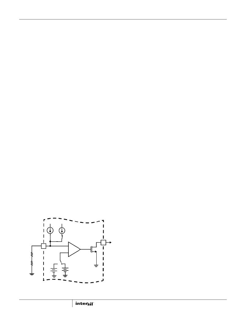
�Voltage� Regulator� Thermal� Throttling�
�Figure� 24� shows� the� thermal� throttling� feature� with� hysteresis.�
�An� NTC� network� is� connected� between� the� NTC� pin� and� GND.� At�
�low� temperature,� SW1� is� on� and� SW2� connects� to� the� 1.20V� side.�
�The� total� current� flowing� out� of� the� NTC� pin� is� 60μA.� The� voltage�
�on� NTC� pin� is� higher� than� the� threshold� voltage� of� 1.20V� and� the�
�comparator� output� is� low.� VR_TT#� is� pulled� up� by� the� external�
�resistor.�
�the� required� temperature� hysteresis� correlates� to� 2.96k� Ω�
�resistance� change.� A� regular� resistor� may� need� to� be� in� series�
�with� the� NTC� thermistor� to� meet� the� threshold� voltage� values.�
�For� example,� given� Panasonic� NTC� thermistor� with� B� =� 4700,� the�
�resistance� will� drop� to� 0.03322� of� its� nominal� at� +105°C,� and�
�drop� to� 0.03956� of� its� nominal� at� +100°C.� If� the� required�
�temperature� hysteresis� is� +105°C� to� +100°C,� the� required�
�resistance� of� NTC� will� be� as� shown� in� Equation� 38:�
�2.96k� Ω�
�(EQ.� 38)�
�Therefore,� a� larger� value� thermistor� such� as� 470k� NTC� should� be�
�used.�
�At� +105°C,� 470k� Ω� NTC� resistance� becomes�
�(0.03322� ×� 470k� Ω� )� =� 15.6k� Ω� .� With� 60μA� on� the� NTC� pin,� the�
�voltage� is� only� (15.6k� Ω� ×� 60μA)� =� 0.937V.� This� value� is� much�
�lower� than� the� threshold� voltage� of� 1.20V.� Therefore,� a� regular�
�resistor� needs� to� be� in� series� with� the� NTC.� The� required�
�resistance� can� be� calculated� by� Equation� 39:�
�(EQ.� 39)�
�60� μ� A�
�4.42k� is� a� standard� resistor� value.� Therefore,� the� NTC� branch� should�
�have� a� 470k� NTC� and� 4.42k� resistor� in� series.� The� part� number� for�
�the� NTC� thermistor� is� ERTJ0EV474J.� It� is� a� 0402� package.� NTC�
�thermistor� will� be� placed� in� the� hot� spot� of� the� board.�
�54μA�
�64μA�
�Layout� Guidelines�
�Table� 5� shows� the� layout� considerations.� The� designators� refer�
�NTC�
�SW1�
�-�
�VR_TT#�
�to� the� reference� designs� shown� in� Figures� 25� and� 26.�
�+�
�V� NTC�
�-�
�R� NTC�
�+�
�R� s�
�1.24V�
�SW2�
�1.20V�
�INTERNAL� TO�
�ISL62881�
�FIGURE� 24.� CIRCUITRY� ASSOCIATED� WITH� THE� THERMAL�
�THROTTLING� FEATURE� OF� THE� ISL62881�
�23�
�FN6924.3�
�June� 16,� 2011�
�相关PDF资料 |
PDF描述 |
|---|---|
| ISL62882IRTZ | IC REG PWM 2PHASE BUCK 40TQFN |
| ISL62883IRTZ | IC REG PWM 3PHASE BUCK 40TQFN |
| ISL6292BCRZ | IC CHARGER LI-ION 4.2V 4X4 16QFN |
| ISL6294IBZ | IC CHRGR LI-ION SGL 8-SOIC |
| ISL6306IRZ | IC REG CTRLR BUCK PWM VM 40-QFN |
相关代理商/技术参数 |
参数描述 |
|---|---|
| ISL62881HRTZ-T | 功能描述:直流/直流开关调节器 1 PHS PWM BUCKG FOR MICROPROCESR PWR SUP RoHS:否 制造商:International Rectifier 最大输入电压:21 V 开关频率:1.5 MHz 输出电压:0.5 V to 0.86 V 输出电流:4 A 输出端数量: 最大工作温度: 安装风格:SMD/SMT 封装 / 箱体:PQFN 4 x 5 |
| ISL62882 | 制造商:INTERSIL 制造商全称:Intersil Corporation 功能描述:Multiphase PWM Regulator for IMVP-6.5 Mobile CPUs and GPUs |
| ISL62882B | 制造商:INTERSIL 制造商全称:Intersil Corporation 功能描述:Multiphase PWM Regulator for IMVP-6.5 Mobile CPUs and GPUs |
| ISL62882BHRTZ | 功能描述:直流/直流开关调节器 2 PHS PWM BUCKG FOR MICROPROC PWR SUP RoHS:否 制造商:International Rectifier 最大输入电压:21 V 开关频率:1.5 MHz 输出电压:0.5 V to 0.86 V 输出电流:4 A 输出端数量: 最大工作温度: 安装风格:SMD/SMT 封装 / 箱体:PQFN 4 x 5 |
| ISL62882BHRTZR5411 | 制造商:Intersil Corporation 功能描述: |
发布紧急采购,3分钟左右您将得到回复。