参数资料
| 型号: | ISL6313CRZ-T |
| 厂商: | Intersil |
| 文件页数: | 10/33页 |
| 文件大小: | 0K |
| 描述: | IC CTRLR PWM 2PHASE BUCK 36-QFN |
| 产品培训模块: | Solutions for Industrial Control Applications |
| 标准包装: | 4,000 |
| 应用: | 控制器,Intel VR11,AMD CPU |
| 输入电压: | 5 V ~ 12 V |
| 输出数: | 1 |
| 输出电压: | 0.5 V ~ 1.6 V |
| 工作温度: | 0°C ~ 70°C |
| 安装类型: | 表面贴装 |
| 封装/外壳: | 36-WFQFN 裸露焊盘 |
| 供应商设备封装: | 36-TQFN 裸露焊盘(6x6) |
| 包装: | 带卷 (TR) |
第1页第2页第3页第4页第5页第6页第7页第8页第9页当前第10页第11页第12页第13页第14页第15页第16页第17页第18页第19页第20页第21页第22页第23页第24页第25页第26页第27页第28页第29页第30页第31页第32页第33页
�� �
�
�ISL6313�
�channel.� Tie� the� ISEN+� pins� to� the� VCORE� side� of� their�
�corresponding� channel’s� sense� capacitor.�
�Tying� ISEN2-� to� VCC� programs� the� part� for� single� phase�
�operation.�
�UGATE1� and� UGATE2�
�Connect� these� pins� to� the� corresponding� upper� MOSFET�
�gates.� These� pins� are� used� to� control� the� upper� MOSFETs�
�and� are� monitored� for� shoot-through� prevention� purposes.�
�BOOT1� and� BOOT2�
�These� pins� provide� the� bias� voltage� for� the� corresponding�
�upper� MOSFET� drives.� Connect� these� pins� to� appropriately�
�chosen� external� bootstrap� capacitors.� Internal� bootstrap�
�diodes� connected� to� the� PVCC� pin� provides� the� necessary�
�bootstrap� charge.�
�PHASE1� and� PHASE2�
�Connect� these� pins� to� the� sources� of� the� corresponding�
�upper� MOSFETs.� These� pins� are� the� return� path� for� the�
�upper� MOSFET� drives.�
�LGATE1� and� LGATE2�
�These� pins� are� used� to� control� the� lower� MOSFETs.� Connect�
�these� pins� to� the� corresponding� lower� MOSFETs’� gates.�
�SS�
�A� resistor,� R� SS� ,� placed� from� SS� to� ground� or� VCC,� will� set�
�the� soft-start� ramp� slope.� Refer� to� Equations� 20� and� 21� for�
�proper� resistor� calculation.�
�The� state� of� the� SS� pin� also� selects� which� of� the� available� DAC�
�tables� will� be� used� to� decode� the� VID� inputs� and� puts� the�
�controller� into� the� corresponding� mode� of� operation.� For� Intel�
�VR11� mode� of� operation� the� R� SS� resistor� should� be� tied� to�
�ground.� AMD� compliance� is� selected� if� the� R� SS� resistor� is� tied�
�to� VCC.�
�PGOOD�
�For� Intel� mode� of� operation,� PGOOD� indicates� whether� VSEN�
�is� within� specified� overvoltage� and� undervoltage� limits� after� a�
�fixed� delay� from� the� end� of� soft-start.� If� VSEN� exceeds� these�
�limits,� an� overcurrent� event� occurs,� or� if� the� part� is� disabled,�
�PGOOD� is� pulled� low.� PGOOD� is� always� low� prior� to� the� end�
�of� soft-start.�
�For� AMD� modes� of� operation,� PGOOD� will� always� be� high�
�as� long� as� VSEN� is� within� the� specified� undervoltage,�
�overvoltage� window� and� soft-start� has� ended.� PGOOD� only�
�goes� low� if� VSEN� is� outside� this� window.�
�Operation�
�only� multi-phase� converters� can� accomplish.� The� ISL6313�
�controller� helps� simplify� implementation� by� integrating� vital�
�functions� and� requiring� minimal� external� components.� The�
�“Block� Diagram”� on� page� 3� provides� a� top� level� view� of�
�multi-phase� power� conversion� using� the� ISL6313� controller.�
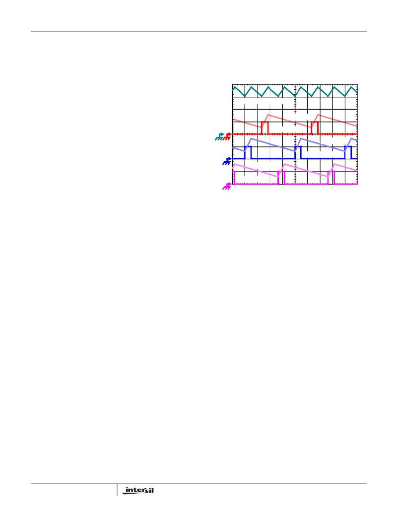
�I� L1� +� I� L2� +� I� L3� ,� 7A/DIV�
�I� L3� ,� 7A/DIV�
�PWM3,� 5V/DIV�
�I� L2� , 7A/DIV�
�PWM2,� 5V/DIV�
�I� L1� ,� 7A/DIV�
�PWM1,� 5V/DIV�
�1� μ� s/DIV�
�FIGURE� 1.� PWM� AND� INDUCTOR-CURRENT� WAVEFORMS�
�FOR� 3-PHASE� CONVERTER�
�Interleaving�
�The� switching� of� each� channel� in� a� multi-phase� converter� is�
�timed� to� be� symmetrically� out� of� phase� with� each� of� the� other�
�channels.� In� a� 3-phase� converter,� each� channel� switches� 1/3�
�cycle� after� the� previous� channel� and� 1/3� cycle� before� the�
�following� channel.� As� a� result,� the� three-phase� converter� has�
�a� combined� ripple� frequency� three� times� greater� than� the�
�ripple� frequency� of� any� one� phase.� In� addition,� the�
�peak-to-peak� amplitude� of� the� combined� inductor� currents� is�
�reduced� in� proportion� to� the� number� of� phases� (Equations� 1�
�and� 2).� Increased� ripple� frequency� and� lower� ripple�
�amplitude� mean� that� the� designer� can� use� less� per-channel�
�inductance� and� lower� total� output� capacitance� for� any�
�performance� specification.�
�Figure� 1� illustrates� the� multiplicative� effect� on� output� ripple�
�frequency.� The� three� channel� currents� (I� L1� ,� I� L2� ,� and� I� L3� )�
�combine� to� form� the� AC� ripple� current� and� the� DC� load�
�current.� The� ripple� component� has� 3x� the� ripple� frequency� of�
�each� individual� channel� current.� Each� PWM� pulse� is�
�terminated� 1/3� of� a� cycle� after� the� PWM� pulse� of� the� previous�
�phase.� The� peak-to-peak� current� for� each� phase� is� about� 7A,�
�and� the� DC� components� of� the� inductor� currents� combine� to�
�feed� the� load.�
�To� understand� the� reduction� of� ripple� current� amplitude� in� the�
�multi-phase� circuit,� examine� the� equation� representing� an�
�individual� channel� peak-to-peak� inductor� current.�
�(� V� IN� –� V� OUT� )� ?� V� OUT�
�L� ?� f� S� ?� V�
�Multiphase� Power� Conversion�
�Microprocessor� load� current� profiles� have� changed� to� the�
�I� PP� =� ----------------------------------------------------------�
�IN�
�(EQ.� 1)�
�point� that� using� single-phase� regulators� is� no� longer� a� viable�
�solution.� Designing� a� regulator� that� is� cost-effective,�
�thermally� sound,� and� efficient� has� become� a� challenge� that�
�10�
�In� Equation� 1,� V� IN� and� V� OUT� are� the� input� and� output�
�voltages� respectively,� L� is� the� single-channel� inductor� value,�
�and� f� S� is� the� switching� frequency.�
�FN6448.2�
�September� 2,� 2008�
�相关PDF资料 |
PDF描述 |
|---|---|
| RMM06DTBN-S664 | CONN EDGECARD 12POS R/A .156 SLD |
| RGM06DTBN-S664 | CONN EDGECARD 12POS R/A .156 SLD |
| RCA30DTAZ-S273 | CONN EDGECARD 60POS R/A .125 SLD |
| 1944-13M | COIL RF 1.0UH MOLDED UNSHIELDED |
| FMM08DRKI | CONN EDGECARD 16POS DIP .156 SLD |
相关代理商/技术参数 |
参数描述 |
|---|---|
| ISL6313IRZ | 功能描述:IC CTRLR PWM 2PHASE BUCK 36-QFN RoHS:是 类别:集成电路 (IC) >> PMIC - 稳压器 - 专用型 系列:- 标准包装:43 系列:- 应用:控制器,Intel VR11 输入电压:5 V ~ 12 V 输出数:1 输出电压:0.5 V ~ 1.6 V 工作温度:-40°C ~ 85°C 安装类型:表面贴装 封装/外壳:48-VFQFN 裸露焊盘 供应商设备封装:48-QFN(7x7) 包装:管件 |
| ISL6313IRZ-T | 功能描述:IC CTRLR PWM 2PHASE BUCK 36-QFN RoHS:是 类别:集成电路 (IC) >> PMIC - 稳压器 - 专用型 系列:- 标准包装:43 系列:- 应用:控制器,Intel VR11 输入电压:5 V ~ 12 V 输出数:1 输出电压:0.5 V ~ 1.6 V 工作温度:-40°C ~ 85°C 安装类型:表面贴装 封装/外壳:48-VFQFN 裸露焊盘 供应商设备封装:48-QFN(7x7) 包装:管件 |
| ISL6314CRZ | 功能描述:电压模式 PWM 控制器 1-PH PWM CNTRLR W/1 INTEGRTD DRVRS 32LD RoHS:否 制造商:Texas Instruments 输出端数量:1 拓扑结构:Buck 输出电压:34 V 输出电流: 开关频率: 工作电源电压:4.5 V to 5.5 V 电源电流:600 uA 最大工作温度:+ 125 C 最小工作温度:- 40 C 封装 / 箱体:WSON-8 封装:Reel |
| ISL6314CRZ-T | 功能描述:IC CTRLR PWM 1PHASE BUCK 32-QFN RoHS:是 类别:集成电路 (IC) >> PMIC - 稳压器 - 专用型 系列:- 标准包装:43 系列:- 应用:控制器,Intel VR11 输入电压:5 V ~ 12 V 输出数:1 输出电压:0.5 V ~ 1.6 V 工作温度:-40°C ~ 85°C 安装类型:表面贴装 封装/外壳:48-VFQFN 裸露焊盘 供应商设备封装:48-QFN(7x7) 包装:管件 |
| ISL6314CRZ-TR5453 | 制造商:Intersil Corporation 功能描述:STD. ISL6314CRZ-T W/GOLD BOND WIRE ONLY T&R - Tape and Reel |
发布紧急采购,3分钟左右您将得到回复。