参数资料
| 型号: | ISL6313CRZ-T |
| 厂商: | Intersil |
| 文件页数: | 26/33页 |
| 文件大小: | 0K |
| 描述: | IC CTRLR PWM 2PHASE BUCK 36-QFN |
| 产品培训模块: | Solutions for Industrial Control Applications |
| 标准包装: | 4,000 |
| 应用: | 控制器,Intel VR11,AMD CPU |
| 输入电压: | 5 V ~ 12 V |
| 输出数: | 1 |
| 输出电压: | 0.5 V ~ 1.6 V |
| 工作温度: | 0°C ~ 70°C |
| 安装类型: | 表面贴装 |
| 封装/外壳: | 36-WFQFN 裸露焊盘 |
| 供应商设备封装: | 36-TQFN 裸露焊盘(6x6) |
| 包装: | 带卷 (TR) |
第1页第2页第3页第4页第5页第6页第7页第8页第9页第10页第11页第12页第13页第14页第15页第16页第17页第18页第19页第20页第21页第22页第23页第24页第25页当前第26页第27页第28页第29页第30页第31页第32页第33页
�� �
�
�ISL6313�
�PVCC�
�BOOT�
�C� GD�
�D�
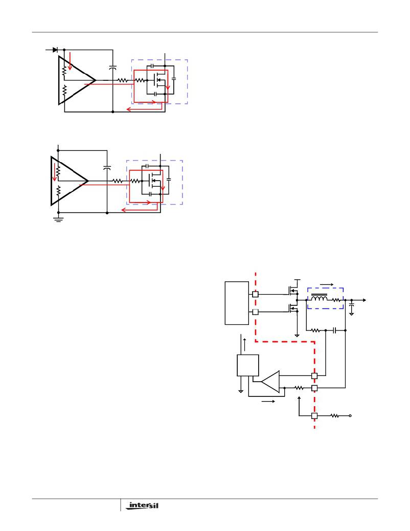
�Inductor� DCR� Current� Sensing� Component�
�Selection�
�The� ISL6313� senses� each� individual� channel’s� inductor�
�current� by� detecting� the� voltage� across� the� output� inductor�
�R� HI1�
�R� LO1�
�UGATE�
�G�
�R� G1�
�R� GI1�
�C� GS�
�C� DS�
�Q� 1�
�DCR� of� that� channel� (As� described� in� the� “Continuous� Current�
��network� is� required� to� accurately� sense� the� inductor� DCR�
�voltage� and� convert� this� information� into� a� current,� which� is�
�S�
�PHASE�
�FIGURE� 18.� TYPICAL� UPPER-GATE� DRIVE� TURN-ON� PATH�
�PVCC�
�D�
�proportional� to� the� total� output� current.� The� time� constant� of�
�this� R-C� network� must� match� the� time� constant� of� the� inductor�
�L/DCR.�
�Follow� the� steps� below� to� choose� the� component� values� for�
�this� RC� network.�
�1.� Choose� an� arbitrary� value� for� C� 1� .� The� recommended�
�R� 1� =� -------------------------�
�R� HI2�
�R� LO2�
�LGATE�
�G�
�R� G2�
�C� GD�
�R� GI2�
�C� GS�
�S�
�C� DS�
�Q� 2�
�value� is� 0.1μF.�
�2.� Plug� the� inductor� L� and� DCR� component� values,� and� the�
�value� for� C� 1� chosen� in� step� 1� into� Equation� 34,� to�
�calculate� the� value� for� R� 1� .�
�L� (EQ.� 34)�
�DCR� ?� C� 1�
�Once� the� R-C� network� components� have� been� chosen,� the�
�effective� internal� R� ISEN� resistance� must� then� be� set.� The�
�FIGURE� 19.� TYPICAL� LOWER-GATE� DRIVE� TURN-ON� PATH�
�The� total� gate� drive� power� losses� are� dissipated� among� the�
�resistive� components� along� the� transition� path� and� in� the�
�bootstrap� diode.� The� portion� of� the� total� power� dissipated� in�
�the� controller� itself� is� the� power� dissipated� in� the� upper� drive�
�R� ISEN� resistance� sets� the� gain� of� the� load� line� regulation�
�loop� as� well� as� the� gain� of� the� channel-current� balance� loop�
�and� the� overcurrent� trip� level.� The� effective� internal� R� ISEN�
�resistance� is� set� through� a� single� resistor� on� the� RSET� pin,�
�R� SET� .�
�path� resistance,� P� DR_UP� ,� the� lower� drive� path� resistance,�
�V� IN�
�IL�
�P� DR_UP� ,� and� in� the� boot� strap� diode,� P� BOOT� .� The� rest� of� the�
�power� will� be� dissipated� by� the� external� gate� resistors� (R� G1�
�MOSFET�
�UGATE�
�L�
�DCR�
�V� OUT�
�and� R� G2� )� and� the� internal� gate� resistors� (R� GI1� and� R� GI2� )� of�
�the� MOSFETs.� Figures� 18� and� 19� show� the� typical� upper� and�
�DRIVER�
�LGATE�
�INDUCTOR�
�V� L� (s)�
�C� OUT�
�lower� gate� drives� turn-on� transition� path.� The� total� power�
�dissipation� in� the� controller� itself,� P� DR� ,� can� be� roughly�
�V� C� (s)�
�estimated� as� Equation� 33:�
�R� 1�
�C� 1�
�P� DR� =� P� DR_UP� +� P� DR_LOW� +� P� BOOT� +� (� I� Q� ?� VCC� )�
�(EQ.� 33)�
�I� n�
�ISL6313� INTERNAL�
�CIRCUIT�
�P� BOOT� =� ---------------------�
�P� DR_UP� =� ?� --------------------------------------� +� ----------------------------------------� ?� ?� ---------------------�
�?� R� HI1� +� R� EXT1� R� LO1� +� R� EXT1� ?�
�P� DR_LOW� =� ?� --------------------------------------� +� ----------------------------------------� ?� ?� ---------------------�
�?� R� HI2� +� R� EXT2� R� LO2� +� R� EXT2� ?�
�P� Qg_Q1�
�3�
�?� R� HI1� R� LO1� ?� P� Qg_Q1�
�?� R� HI2� R� LO2� ?� P� Qg_Q2�
�3�
�2�
�SENSE�
�I� SEN�
�+�
�-�
�V� C� (s)�
�R� ISEN�
�ISEN-�
�ISEN+�
�RSET�
�R� SET�
�VCC�
�R� EXT1� =� R� G1� +� -------------�
�N�
�R� EXT2� =� R� G2� +� -------------�
�N�
�R� GI1�
�Q1�
�26�
�R� GI2�
�Q2�
�FIGURE� 20.� DCR� SENSING� CONFIGURATION�
�Use� Equation� 35� to� calculate� the� value� of� R� SET� .� In�
�this� equation,� DCR� is� the� DCR� of� the� output� inductor� at� room�
�temperature,� I� OCP� is� the� desired� overcurrent� trip� level,� and�
�N� is� the� number� of� phases.� It� is� recommended� that� the�
�FN6448.2�
�September� 2,� 2008�
�相关PDF资料 |
PDF描述 |
|---|---|
| RMM06DTBN-S664 | CONN EDGECARD 12POS R/A .156 SLD |
| RGM06DTBN-S664 | CONN EDGECARD 12POS R/A .156 SLD |
| RCA30DTAZ-S273 | CONN EDGECARD 60POS R/A .125 SLD |
| 1944-13M | COIL RF 1.0UH MOLDED UNSHIELDED |
| FMM08DRKI | CONN EDGECARD 16POS DIP .156 SLD |
相关代理商/技术参数 |
参数描述 |
|---|---|
| ISL6313IRZ | 功能描述:IC CTRLR PWM 2PHASE BUCK 36-QFN RoHS:是 类别:集成电路 (IC) >> PMIC - 稳压器 - 专用型 系列:- 标准包装:43 系列:- 应用:控制器,Intel VR11 输入电压:5 V ~ 12 V 输出数:1 输出电压:0.5 V ~ 1.6 V 工作温度:-40°C ~ 85°C 安装类型:表面贴装 封装/外壳:48-VFQFN 裸露焊盘 供应商设备封装:48-QFN(7x7) 包装:管件 |
| ISL6313IRZ-T | 功能描述:IC CTRLR PWM 2PHASE BUCK 36-QFN RoHS:是 类别:集成电路 (IC) >> PMIC - 稳压器 - 专用型 系列:- 标准包装:43 系列:- 应用:控制器,Intel VR11 输入电压:5 V ~ 12 V 输出数:1 输出电压:0.5 V ~ 1.6 V 工作温度:-40°C ~ 85°C 安装类型:表面贴装 封装/外壳:48-VFQFN 裸露焊盘 供应商设备封装:48-QFN(7x7) 包装:管件 |
| ISL6314CRZ | 功能描述:电压模式 PWM 控制器 1-PH PWM CNTRLR W/1 INTEGRTD DRVRS 32LD RoHS:否 制造商:Texas Instruments 输出端数量:1 拓扑结构:Buck 输出电压:34 V 输出电流: 开关频率: 工作电源电压:4.5 V to 5.5 V 电源电流:600 uA 最大工作温度:+ 125 C 最小工作温度:- 40 C 封装 / 箱体:WSON-8 封装:Reel |
| ISL6314CRZ-T | 功能描述:IC CTRLR PWM 1PHASE BUCK 32-QFN RoHS:是 类别:集成电路 (IC) >> PMIC - 稳压器 - 专用型 系列:- 标准包装:43 系列:- 应用:控制器,Intel VR11 输入电压:5 V ~ 12 V 输出数:1 输出电压:0.5 V ~ 1.6 V 工作温度:-40°C ~ 85°C 安装类型:表面贴装 封装/外壳:48-VFQFN 裸露焊盘 供应商设备封装:48-QFN(7x7) 包装:管件 |
| ISL6314CRZ-TR5453 | 制造商:Intersil Corporation 功能描述:STD. ISL6314CRZ-T W/GOLD BOND WIRE ONLY T&R - Tape and Reel |
发布紧急采购,3分钟左右您将得到回复。