参数资料
| 型号: | ISL6313CRZ-T |
| 厂商: | Intersil |
| 文件页数: | 28/33页 |
| 文件大小: | 0K |
| 描述: | IC CTRLR PWM 2PHASE BUCK 36-QFN |
| 产品培训模块: | Solutions for Industrial Control Applications |
| 标准包装: | 4,000 |
| 应用: | 控制器,Intel VR11,AMD CPU |
| 输入电压: | 5 V ~ 12 V |
| 输出数: | 1 |
| 输出电压: | 0.5 V ~ 1.6 V |
| 工作温度: | 0°C ~ 70°C |
| 安装类型: | 表面贴装 |
| 封装/外壳: | 36-WFQFN 裸露焊盘 |
| 供应商设备封装: | 36-TQFN 裸露焊盘(6x6) |
| 包装: | 带卷 (TR) |
第1页第2页第3页第4页第5页第6页第7页第8页第9页第10页第11页第12页第13页第14页第15页第16页第17页第18页第19页第20页第21页第22页第23页第24页第25页第26页第27页当前第28页第29页第30页第31页第32页第33页
�� �
�
�ISL6313�
�C� 2� (OPTIONAL)�
�--------------------------------� >� f� 0�
�Case� 1:�
�1�
�2� ?� π� ?� L� ?� C�
�R� C� =� R� FB� ?� ----------------------------------------------------------�
�V�
�2� ?� π� ?� V� P-P� ?� R� FB� ?� f� 0�
�R� C�
�C� C�
�COMP�
�FB�
�ISL6313�
�2� ?� π� ?� f� 0� ?� V� P-P� ?� L� ?� C�
�IN�
�V� IN�
�C� C� =� ------------------------------------------------------�
�R� FB�
�--------------------------------� ≤� f� 0� <� -------------------------------------�
�VSEN�
�Case� 2:�
�1� 1�
�2� ?� π� ?� L� ?� C� 2� ?� π� ?� C� ?� ESR�
�V� P-P� ?� (� 2� ?� π� )� 2� ?� f� 02� ?� L� ?� C�
�C� C� =� ---------------------------------------------------------------------------------------�
�P-P� ?� R� FB� ?�
�(� 2� ?� π� )� 2� ?� f� 2� ?� V� L� ?� C�
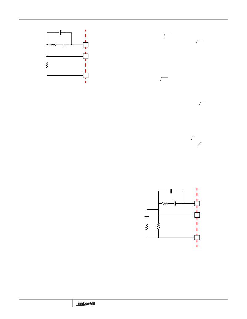
�FIGURE� 22.� COMPENSATION� CONFIGURATION� FOR�
�LOAD-LINE� REGULATED� ISL6313� CIRCUIT�
�Since� the� system� poles� and� zero� are� affected� by� the� values�
�of� the� components� that� are� meant� to� compensate� them,� the�
�solution� to� the� system� equation� becomes� fairly� complicated.�
�V�
�R� C� =� R� FB� ?� ------------------------------------------------------------------�
�IN�
�V� IN�
�0�
�(EQ.� 41)�
�f� 0� >� -------------------------------------�
�R� C� =� R� FB� ?� ----------------------------------------------�
�V� ?� ESR�
�2� ?� π� ?� V� P-P� ?� R� FB� ?� f� 0� ?� L�
�Fortunately,� there� is� a� simple� approximation� that� comes� very�
�close� to� an� optimal� solution.� Treating� the� system� as� though� it�
�were� a� voltage-mode� regulator,� by� compensating� the� L-C�
�poles� and� the� ESR� zero� of� the� voltage� mode� approximation,�
�yields� a� solution� that� is� always� stable� with� very� close� to� ideal�
�transient� performance.�
�Select� a� target� bandwidth� for� the� compensated� system,� f� 0� .�
�The� target� bandwidth� must� be� large� enough� to� assure�
�Case� 3:�
�1�
�2� ?� π� ?� C� ?� ESR�
�2� ?� π� ?� f� 0� ?� V� P-P� ?� L�
�IN�
�V� IN� ?� ESR� ?� C�
�C� C� =� ------------------------------------------------------------------�
�adequate� transient� performance,� but� smaller� than� 1/3� of� the�
�per-channel� switching� frequency.� The� values� of� the�
�compensation� components� depend� on� the� relationships� of� f� 0�
�to� the� L-C� pole� frequency� and� the� ESR� zero� frequency.� For�
�each� of� the� following� three,� there� is� a� separate� set� of�
�equations� for� the� compensation� components.�
�In� Equation� 41,� L� is� the� per-channel� filter� inductance� divided�
�by� the� number� of� active� channels;� C� is� the� sum� total� of� all�
�COMPENSATION� WITHOUT� LOAD-LINE� REGULATION�
�The� non� load-line� regulated� converter� is� accurately� modeled�
�as� a� voltage-mode� regulator� with� two� poles� at� the� L-C�
�resonant� frequency� and� a� zero� at� the� ESR� frequency.� A�
�type� III� controller,� as� shown� in� Figure� 23,� provides� the�
�necessary� compensation.�
�C� 2�
�output� capacitors;� ESR� is� the� equivalent� series� resistance� of�
�the� bulk� output� filter� capacitance;� and� V� P-P� is� the�
�R� C�
�C� C�
�COMP�
�peak-to-peak� sawtooth� signal� amplitude� as� described� in� the�
�“Electrical� Specifications”� on� page� 6.�
�FB�
�Once� selected,� the� compensation� values� in� Equation� 41�
�assure� a� stable� converter� with� reasonable� transient�
�performance.� In� most� cases,� transient� performance� can� be�
�improved� by� making� adjustments� to� R� C� .� Slowly� increase� the�
�value� of� R� C� while� observing� the� transient� performance� on� an�
�oscilloscope� until� no� further� improvement� is� noted.� Normally,�
�C� 1�
�R� 1�
�R� FB�
�VSEN�
�ISL6313�
�C� C� will� not� need� adjustment.� Keep� the� value� of� C� C� from�
�Equation� 41� unless� some� performance� issue� is� noted.�
�The� optional� capacitor� C� 2� ,� is� sometimes� needed� to� bypass�
�noise� away� from� the� PWM� comparator� (see� Figure� 22).� Keep�
�a� position� available� for� C� 2� ,� and� be� prepared� to� install� a�
�high-frequency� capacitor� of� between� 22pF� and� 150pF� in�
�case� any� leading� edge� jitter� problem� is� noted.�
�28�
�FIGURE� 23.� COMPENSATION� CIRCUIT� WITHOUT� LOAD-LINE�
�REGULATION�
�The� first� step,� is� to� choose� the� desired� bandwidth,� f� 0� ,� of� the�
�compensated� system.� Choose� a� frequency� high� enough� to�
�assure� adequate� transient� performance� but� not� higher� than�
�1/3� of� the� switching� frequency.� The� type-III� compensator� has�
�an� extra� high-frequency� pole,� f� HF� .� This� pole� can� be� used� for�
�added� noise� rejection� or� to� assure� adequate� attenuation� at�
�the� error-amplifier� high-order� pole� and� zero� frequencies.� A�
�FN6448.2�
�September� 2,� 2008�
�相关PDF资料 |
PDF描述 |
|---|---|
| RMM06DTBN-S664 | CONN EDGECARD 12POS R/A .156 SLD |
| RGM06DTBN-S664 | CONN EDGECARD 12POS R/A .156 SLD |
| RCA30DTAZ-S273 | CONN EDGECARD 60POS R/A .125 SLD |
| 1944-13M | COIL RF 1.0UH MOLDED UNSHIELDED |
| FMM08DRKI | CONN EDGECARD 16POS DIP .156 SLD |
相关代理商/技术参数 |
参数描述 |
|---|---|
| ISL6313IRZ | 功能描述:IC CTRLR PWM 2PHASE BUCK 36-QFN RoHS:是 类别:集成电路 (IC) >> PMIC - 稳压器 - 专用型 系列:- 标准包装:43 系列:- 应用:控制器,Intel VR11 输入电压:5 V ~ 12 V 输出数:1 输出电压:0.5 V ~ 1.6 V 工作温度:-40°C ~ 85°C 安装类型:表面贴装 封装/外壳:48-VFQFN 裸露焊盘 供应商设备封装:48-QFN(7x7) 包装:管件 |
| ISL6313IRZ-T | 功能描述:IC CTRLR PWM 2PHASE BUCK 36-QFN RoHS:是 类别:集成电路 (IC) >> PMIC - 稳压器 - 专用型 系列:- 标准包装:43 系列:- 应用:控制器,Intel VR11 输入电压:5 V ~ 12 V 输出数:1 输出电压:0.5 V ~ 1.6 V 工作温度:-40°C ~ 85°C 安装类型:表面贴装 封装/外壳:48-VFQFN 裸露焊盘 供应商设备封装:48-QFN(7x7) 包装:管件 |
| ISL6314CRZ | 功能描述:电压模式 PWM 控制器 1-PH PWM CNTRLR W/1 INTEGRTD DRVRS 32LD RoHS:否 制造商:Texas Instruments 输出端数量:1 拓扑结构:Buck 输出电压:34 V 输出电流: 开关频率: 工作电源电压:4.5 V to 5.5 V 电源电流:600 uA 最大工作温度:+ 125 C 最小工作温度:- 40 C 封装 / 箱体:WSON-8 封装:Reel |
| ISL6314CRZ-T | 功能描述:IC CTRLR PWM 1PHASE BUCK 32-QFN RoHS:是 类别:集成电路 (IC) >> PMIC - 稳压器 - 专用型 系列:- 标准包装:43 系列:- 应用:控制器,Intel VR11 输入电压:5 V ~ 12 V 输出数:1 输出电压:0.5 V ~ 1.6 V 工作温度:-40°C ~ 85°C 安装类型:表面贴装 封装/外壳:48-VFQFN 裸露焊盘 供应商设备封装:48-QFN(7x7) 包装:管件 |
| ISL6314CRZ-TR5453 | 制造商:Intersil Corporation 功能描述:STD. ISL6314CRZ-T W/GOLD BOND WIRE ONLY T&R - Tape and Reel |
发布紧急采购,3分钟左右您将得到回复。