参数资料
| 型号: | ISL6323BCRZ-T |
| 厂商: | Intersil |
| 文件页数: | 30/36页 |
| 文件大小: | 0K |
| 描述: | IC PWM CTRLR SYNC BUCK DL 48QFN |
| 标准包装: | 4,000 |
| 应用: | 控制器,AMD SVI |
| 输入电压: | 5 V ~ 12 V |
| 输出数: | 2 |
| 输出电压: | 最高 2V |
| 工作温度: | 0°C ~ 70°C |
| 安装类型: | 表面贴装 |
| 封装/外壳: | 48-VFQFN 裸露焊盘 |
| 供应商设备封装: | 48-QFN(7x7) |
| 包装: | 带卷 (TR) |
第1页第2页第3页第4页第5页第6页第7页第8页第9页第10页第11页第12页第13页第14页第15页第16页第17页第18页第19页第20页第21页第22页第23页第24页第25页第26页第27页第28页第29页当前第30页第31页第32页第33页第34页第35页第36页
�� �
�
�ISL6323B�
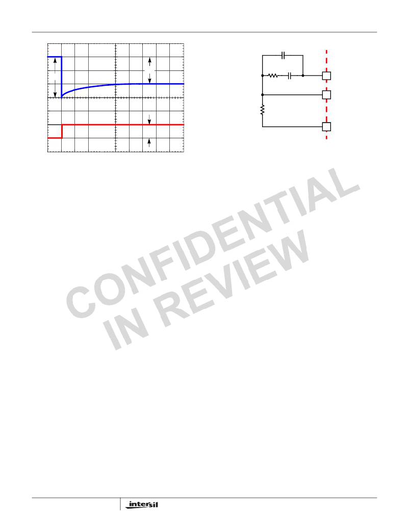
�C� 2� (OPTIONAL)�
�Δ� V� 1�
�Δ� V� 2�
�R� C�
�C� C�
�COMP�
�V� OUT�
�I� TRAN�
�R� FB�
�FB�
�VSEN�
�ISL6323B�
�Δ� I�
�FIGURE� 22.� COMPENSATION� CONFIGURATION� FOR�
�LOAD-LINE� REGULATED� ISL6323B� CIRCUIT�
�FIGURE� 21.� TIME� CONSTANT� MISMATCH� BEHAVIOR�
�4.� Select� new� values,� R� 1,NEW� and� R� 2,NEW� ,� for� the� time�
�constant� resistors� based� on� the� original� values,� R� 1,OLD�
�Since� the� system� poles� and� zero� are� affected� by� the� values�
�of� the� components� that� are� meant� to� compensate� them,� the�
�solution� to� the� system� equation� becomes� fairly� complicated.�
�Fortunately,� there� is� a� simple� approximation� that� comes� very�
�Δ� V� 2�
�Δ� V� 2�
�and� R� 2,OLD� ,� using� Equations� 48� and� 49.�
�Δ� V� 1�
�R� 1� ,� NEW� =� R� 1� ,� OLD� ?� -----------�
�Δ� V� 1�
�R� 2� ,� NEW� =� R� 2� ,� OLD� ?� -----------�
�(EQ.� 48)�
�(EQ.� 49)�
�close� to� an� optimal� solution.� Treating� the� system� as� though� it�
�were� a� voltage-mode� regulator,� by� compensating� the� L-C�
�poles� and� the� ESR� zero� of� the� voltage� mode� approximation,�
�yields� a� solution� that� is� always� stable� with� very� close� to� ideal�
�transient� performance.�
�Select� a� target� bandwidth� for� the� compensated� system,� f� 0� .�
�5.� Replace� R� 1� and� R� 2� with� the� new� values� and� check� to� see�
�that� the� error� is� corrected.� Repeat� the� procedure� if�
�necessary.�
�Loadline� Regulation� Resistor�
�The� loadline� regulation� resistor,� labeled� R� FB� in� Figure� 8,�
�sets� the� desired� loadline� required� for� the� application.�
�The� target� bandwidth� must� be� large� enough� to� assure�
�adequate� transient� performance,� but� smaller� than� 1/3� of� the�
�per-channel� switching� frequency.� The� values� of� the�
�compensation� components� depend� on� the� relationships� of� f� 0�
�to� the� L-C� pole� frequency� and� the� ESR� zero� frequency.� For�
�each� of� the� following� three,� there� is� a� separate� set� of�
�equations� for� the� compensation� components.�
�V� DROOP�
�R� FB� =� ----------------------------------------------------------------------�
�I� OUT�
�----------� ?� --------------------------� ?� ---------------� ?� K�
�R� SET�
�Equation� 50� can� be� used� to� calculate� R� FB� .�
�MAX�
�400� MAX� DCR�
�3� N�
�(EQ.� 50)�
�In� Equation� 51,� L� is� the� per-channel� filter� inductance� divided�
�by� the� number� of� active� channels;� C� is� the� sum� total� of� all�
�output� capacitors;� ESR� is� the� equivalent� series� resistance� of�
�the� bulk� output� filter� capacitance;� and� V� PP� is� the�
�peak-to-peak� sawtooth� signal� amplitude� as� described� in� the�
�Where� R� ISEN� is� the� 2.4k� Ω� internal� current� sense� resistor,� K� I�
�is� defined� in� Equation� 10� and� K� is� defined� in� Equation� 7.�
�If� no� loadline� regulation� is� required,� FS� resistor� should� be�
�tied� between� the� FS� pin� and� VCC.� To� choose� the� value� for�
�R� FB� in� this� situation,� please� refer� to� “Compensation� Without�
��Compensation� With� Loadline� Regulation�
�The� load-line� regulated� converter� behaves� in� a� similar�
�manner� to� a� peak� current� mode� controller� because� the� two�
�poles� at� the� output� filter� L-C� resonant� frequency� split� with� the�
�introduction� of� current� information� into� the� control� loop.� The�
�final� location� of� these� poles� is� determined� by� the� system�
�function,� the� gain� of� the� current� signal,� and� the� value� of� the�
�compensation� components,� R� C� and� C� C� .�
�30�
��Once� selected,� the� compensation� values� in� Equation� 51�
�assure� a� stable� converter� with� reasonable� transient�
�performance.� In� most� cases,� transient� performance� can� be�
�improved� by� making� adjustments� to� R� C� .� Slowly� increase� the�
�value� of� R� C� while� observing� the� transient� performance� on� an�
�oscilloscope� until� no� further� improvement� is� noted.� Normally,�
�C� C� will� not� need� adjustment.� Keep� the� value� of� C� C� from�
�Equation� 51� unless� some� performance� issue� is� noted.�
�The� optional� capacitor� C� 2� ,� is� sometimes� needed� to� bypass�
�noise� away� from� the� PWM� comparator� (see� Figure� 22).� Keep�
�a� position� available� for� C� 2� ,� and� be� prepared� to� install� a�
�high-frequency� capacitor� of� between� 22pF� and� 150pF� in�
�case� any� leading� edge� jitter� problem� is� noted.�
�FN6879.1�
�May� 12,� 2010�
�相关PDF资料 |
PDF描述 |
|---|---|
| ISL6323ACRZ-T | IC PWM CTRLR SYNC BUCK DL 48QFN |
| ESM36DRSH | CONN EDGECARD 72POS DIP .156 SLD |
| LT1529CQ-3.3#PBF | IC REG LDO 3.3V 3A DDPAK-5 |
| LT1764AET-3.3#PBF | IC REG LDO 3.3V 3A TO220-5 |
| ISL6323CRZ-T | IC HYBRID CTRLR PWM MONO 48-QFN |
相关代理商/技术参数 |
参数描述 |
|---|---|
| ISL6323BCRZ-TR5381 | 制造商:Intersil Corporation 功能描述:4+1 PHASE CONT. FOR CORE+NORTHBRIDGE, 2 PHASE PSI, 3.4MHZ S - Tape and Reel 制造商:Intersil Corporation 功能描述:IC PWM CTRLR SYNC BUCK DL 48QFN 制造商:Intersil 功能描述:4+1 PHS CONT CORE + NORTHBRDG PROG |
| ISL6323BCRZ-TR5453 | 制造商:Intersil Corporation 功能描述:STD. ISL6323BCRZ-T WITH GOLD BOND WIRE ONLY, T&R - Tape and Reel |
| ISL6323BIRZ | 功能描述:IC PWM CTRLR SYNC BUCK DL 48QFN RoHS:是 类别:集成电路 (IC) >> PMIC - 稳压器 - 专用型 系列:- 标准包装:43 系列:- 应用:控制器,Intel VR11 输入电压:5 V ~ 12 V 输出数:1 输出电压:0.5 V ~ 1.6 V 工作温度:-40°C ~ 85°C 安装类型:表面贴装 封装/外壳:48-VFQFN 裸露焊盘 供应商设备封装:48-QFN(7x7) 包装:管件 |
| ISL6323BIRZR5381 | 制造商:Intersil Corporation 功能描述:4+1 PHASE CONT. FOR CORE+NORTHBRIDGE, 2 PHASE PSI, 3.4MHZ SV - Rail/Tube 制造商:Intersil Corporation 功能描述:IC PWM CTRLR SYNC BUCK DL 48QFN 制造商:Intersil 功能描述:4+1 PHS CONT CORE + NORTHBRDG PROG |
| ISL6323BIRZ-T | 功能描述:IC PWM CTRLR SYNC BUCK DL 48QFN RoHS:是 类别:集成电路 (IC) >> PMIC - 稳压器 - 专用型 系列:- 标准包装:43 系列:- 应用:控制器,Intel VR11 输入电压:5 V ~ 12 V 输出数:1 输出电压:0.5 V ~ 1.6 V 工作温度:-40°C ~ 85°C 安装类型:表面贴装 封装/外壳:48-VFQFN 裸露焊盘 供应商设备封装:48-QFN(7x7) 包装:管件 |
发布紧急采购,3分钟左右您将得到回复。