- 您现在的位置:买卖IC网 > PDF目录15164 > ISL6326BCRZ-T (Intersil)IC REG CTRLR BUCK PWM VM 40-QFN PDF资料下载
参数资料
| 型号: | ISL6326BCRZ-T |
| 厂商: | Intersil |
| 文件页数: | 19/30页 |
| 文件大小: | 0K |
| 描述: | IC REG CTRLR BUCK PWM VM 40-QFN |
| 标准包装: | 4,000 |
| PWM 型: | 电压模式 |
| 输出数: | 1 |
| 频率 - 最大: | 275kHz |
| 占空比: | 25% |
| 电源电压: | 4.75 V ~ 5.25 V |
| 降压: | 是 |
| 升压: | 无 |
| 回扫: | 无 |
| 反相: | 无 |
| 倍增器: | 无 |
| 除法器: | 无 |
| Cuk: | 无 |
| 隔离: | 无 |
| 工作温度: | 0°C ~ 70°C |
| 封装/外壳: | 40-VFQFN 裸露焊盘 |
| 包装: | 带卷 (TR) |
第1页第2页第3页第4页第5页第6页第7页第8页第9页第10页第11页第12页第13页第14页第15页第16页第17页第18页当前第19页第20页第21页第22页第23页第24页第25页第26页第27页第28页第29页第30页
�� �
�
�ISL6326B�
�Dynamic� VID�
�Modern� microprocessors� need� to� make� changes� to� their�
�core� voltage� as� part� of� normal� operation.� They� direct� the�
�core-voltage� regulator� to� do� this� by� making� changes� to� the�
�VID� inputs� during� regulator� operation.� The� power�
�ISL66xx� family� of� Intersil� MOSFET� drivers,� which� require�
�12V� bias.�
�3.� The� voltage� on� EN_VTT� must� be� higher� than� 0.875V� to�
�enable� the� controller.� This� pin� is� typically� connected� to� the�
�output� of� VTT� VR.�
�management� solution� is� required� to� monitor� the� DAC� inputs�
�and� respond� to� on-the-fly� VID� changes� in� a� controlled�
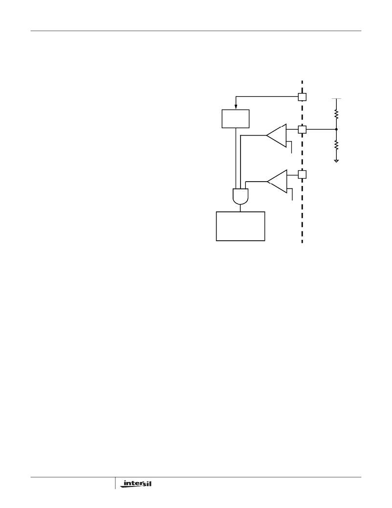
�ISL6326B� INTERNAL� CIRCUIT�
�EXTERNAL� CIRCUIT�
�manner.� Supervising� the� safe� output� voltage� transition� within�
�the� DAC� range� of� the� processor� without� discontinuity� or�
�VCC�
�+� 12� V�
�disruption� is� a� necessary� function� of� the� core-voltage�
�regulator.�
�In� order� to� ensure� the� smooth� transition� of� output� voltage�
�during� VID� change,� a� VID� step� change� smoothing� network,�
�composed� of� R� REF� and� C� REF� as� shown� in� Figure� 6,� can� be�
�used.� The� selection� of� R� REF� is� based� on� the� desired� offset�
�POR�
�CIRCUIT�
�ENABLE�
�COMPARATOR�
�+�
�-�
�0.875V�
�10k� Ω�
�EN_PWR�
�91� 0Ω�
�voltage� as� detailed� above� in� Output-Voltage� Offset�
�Programming� .� The� selection� of� C� REF� is� based� on� the� time�
�duration� for� 1� bit� VID� change� and� the� allowable� delay� time.�
�Assuming� the� microprocessor� controls� the� VID� change� at� 1�
�bit� every� T� VID� ,� the� relationship� between� the� time� constant� of�
�R� REF� and� C� REF� network� and� T� VID� is� given� by� the� following�
�equation.�
�+�
�-�
�0.875V�
�EN_VTT�
�C� REF� R� REF� =� T� VID�
�(EQ.� 13)�
�SOFT-START�
�AND�
�FAULT� LOGIC�
�Operation� Initialization�
�Prior� to� converter� initialization,� proper� conditions� must� exist�
�on� the� enable� inputs� and� VCC.� When� the� conditions� are� met,�
�the� controller� begins� soft-start.� Once� the� output� voltage� is�
�within� the� proper� window� of� operation,� VR_RDY� asserts�
�logic� high.�
�Enable� and� Disable�
�While� in� shutdown� mode,� the� PWM� outputs� are� held� in� a�
�high-impedance� state� to� assure� the� drivers� remain� off.� The�
�following� input� conditions� must� be� met� before� the� ISL6326B�
�is� released� from� shutdown� mode.�
�1.� The� bias� voltage� applied� at� VCC� must� reach� the� internal�
�power-on� reset� (POR)� rising� threshold.� Once� this�
�threshold� is� reached,� proper� operation� of� all� aspects� of�
�the� ISL6326B� is� guaranteed.� Hysteresis� between� the�
�rising� and� falling� thresholds� assure� that� once� enabled,�
�the� ISL6326B� will� not� inadvertently� turn� off� unless� the�
�bias� voltage� drops� substantially� (see� Electrical�
�Specifications� ).�
�2.� The� ISL6326B� features� an� enable� input� (EN_PWR)� for�
�power� sequencing� between� the� controller� bias� voltage�
�and� another� voltage� rail.� The� enable� comparator� holds�
�the� ISL6326B� in� shutdown� until� the� voltage� at� EN_PWR�
�rises� above� 0.875V.� The� enable� comparator� has� about�
�FIGURE� 7.� POWER� SEQUENCING� USING� THRESHOLD-�
�SENSITIVE� ENABLE� (EN)� FUNCTION�
�When� all� conditions� above� are� satisfied,� ISL6326B� begins�
�the� soft-start� and� ramps� the� output� voltage� to� 1.1V� first.� After�
�remaining� at� 1.1V� for� some� time,� ISL6326B� reads� the� VID�
�code� at� VID� input� pins.� If� the� VID� code� is� valid,� ISL6326B� will�
�regulate� the� output� to� the� final� VID� setting.� If� the� VID� code� is�
�OFF� code,� ISL6326B� will� shut� down,� and� cycling� VCC,�
�EN_PWR� or� EN_VTT� is� needed� to� restart.�
�Soft-Start�
�ISL6326B� based� VR� has� 4� periods� during� soft-start� as�
�shown� in� Figure� 8.� After� VCC,� EN_VTT� and� EN_PWR� reach�
�their� POR/enable� thresholds,� The� controller� will� have� fixed�
�delay� period� TD1.� After� this� delay� period,� the� VR� will� begin�
�first� soft-start� ramp� until� the� output� voltage� reaches� 1.1V�
�Vboot� voltage.� Then,� the� controller� will� regulate� the� VR�
�voltage� at� 1.1V� for� another� fixed� period� TD3.� At� the� end� of�
�TD3� period,� ISL6326B� reads� the� VID� signals.� If� the� VID� code�
�is� valid,� ISL6326B� will� initiate� the� second� soft-start� ramp� until�
�the� voltage� reaches� the� VID� voltage� minus� offset� voltage.�
�The� soft-start� time� is� the� sum� of� the� 4� periods� as� shown� in�
�the� following� equation.�
�130mV� of� hysteresis� to� prevent� bounce.� It� is� important�
�that� the� driver� ICs� reach� their� POR� level� before� the�
�ISL6326B� becomes� enabled.� The� schematic� in� Figure� 7�
�T� SS� =� TD1� +� TD2� +� TD3� +� TD4�
�(EQ.� 14)�
�demonstrates� sequencing� the� ISL6326B� with� the�
�19�
�TD1� is� a� fixed� delay� with� the� typical� value� as� 1.36ms.� TD3� is�
�determined� by� the� fixed� 85μs� plus� the� time� to� obtain� valid�
�FN9286.0�
�April� 21,� 2006�
�相关PDF资料 |
PDF描述 |
|---|---|
| H2BBG-10102-G4-ND | JUMPER-H1501TR/A2015G/H1501TR 2" |
| ISL9506HRZ-T | IC REG CTRLR BUCK PWM 40-QFN |
| VE-J51-EY-F4 | CONVERTER MOD DC/DC 12V 50W |
| RGM08DTAS-S189 | CONN EDGECARD 16POS R/A .156 SLD |
| H2BBG-10102-B4-ND | JUMPER-H1501TR/A2015B/H1501TR 2" |
相关代理商/技术参数 |
参数描述 |
|---|---|
| ISL6326BIRZ | 功能描述:电流型 PWM 控制器 W/ANNEAL 4-PHS VR11 CNTRLR IND RoHS:否 制造商:Texas Instruments 开关频率:27 KHz 上升时间: 下降时间: 工作电源电压:6 V to 15 V 工作电源电流:1.5 mA 输出端数量:1 最大工作温度:+ 105 C 安装风格:SMD/SMT 封装 / 箱体:TSSOP-14 |
| ISL6326BIRZ-T | 功能描述:电流型 PWM 控制器 W/ANNEAL 4-PHS VR11 CNTRLR IND RoHS:否 制造商:Texas Instruments 开关频率:27 KHz 上升时间: 下降时间: 工作电源电压:6 V to 15 V 工作电源电流:1.5 mA 输出端数量:1 最大工作温度:+ 105 C 安装风格:SMD/SMT 封装 / 箱体:TSSOP-14 |
| ISL6326CRZ | 功能描述:电流型 PWM 控制器 W/ANNEAL 4-PHS VR11 CNTRLR COM RoHS:否 制造商:Texas Instruments 开关频率:27 KHz 上升时间: 下降时间: 工作电源电压:6 V to 15 V 工作电源电流:1.5 mA 输出端数量:1 最大工作温度:+ 105 C 安装风格:SMD/SMT 封装 / 箱体:TSSOP-14 |
| ISL6326CRZ-T | 功能描述:电流型 PWM 控制器 W/ANNEAL 4-PHS VR11 CNTRLR COM RoHS:否 制造商:Texas Instruments 开关频率:27 KHz 上升时间: 下降时间: 工作电源电压:6 V to 15 V 工作电源电流:1.5 mA 输出端数量:1 最大工作温度:+ 105 C 安装风格:SMD/SMT 封装 / 箱体:TSSOP-14 |
| ISL6326CRZ-TR5453 | 制造商:Intersil Corporation 功能描述:STD. ISL6326CRZ-T W/GOLD BOND WIRE ONLY - Tape and Reel |
发布紧急采购,3分钟左右您将得到回复。