参数资料
| 型号: | ISL6422BEVEZ-T |
| 厂商: | Intersil |
| 文件页数: | 11/18页 |
| 文件大小: | 0K |
| 描述: | IC VREG DUAL LNB W/I2C 38EPTSSOP |
| 标准包装: | 2,500 |
| 应用: | 转换器,卫星信号接收机顶盒设计 |
| 输入电压: | 8 V ~ 14 V |
| 输出数: | 2 |
| 输出电压: | 13.3 V ~ 18.3 V,14.3 V ~ 19.3 V |
| 工作温度: | -20°C ~ 85°C |
| 安装类型: | 表面贴装 |
| 封装/外壳: | 38-TFSOP (0.173",4.40mm 宽)裸露焊盘 |
| 供应商设备封装: | 38-TSSOP 裸露焊盘 |
| 包装: | 带卷 (TR) |
�� �
�
�ISL6422B�
�be� reached� early� in� the� soft-start� cycle� and� a� 51ms� shutdown�
�TABLE� 1.�
�timer� will� be� started� again.� If� the� fault� is� still� present� at� the�
�end� of� the� 51ms,� the� OLF� bit� is� again� set� high� and� the� device�
�once� again� enters� the� 900ms� OFF� time.� This� dynamic�
�operation� can� greatly� reduce� the� power� dissipation� in� a� short�
�circuit� condition,� still� ensuring� excellent� power-on� start-up� in�
�most� conditions.�
�However,� there� could� be� some� cases� in� which� a� highly�
�capacitive� load� on� the� output� may� cause� a� difficult� start-up�
�when� the� dynamic� protection� is� chosen.� This� can� be� solved�
�by� initiating� any� power� start-up� in� static� mode� (DCL� =� HIGH)�
�and� then� switching� to� the� dynamic� mode� (DCL� =� LOW)� after�
�a� chosen� amount� of� time.� When� in� static� mode,� the� OLF1,�
�OLF2� bit� goes� HIGH� when� the� current� clamp� limit� is� reached�
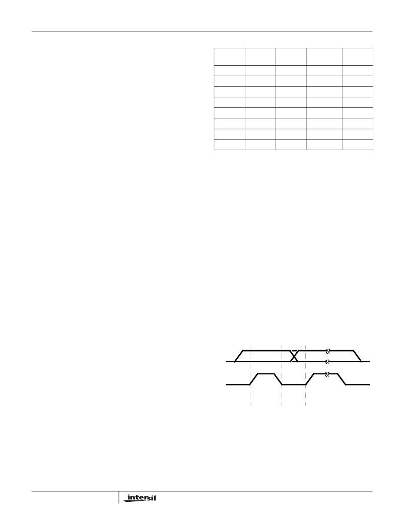
�VSPEN1/2�
�0�
�0�
�0�
�0�
�1�
�1�
�1�
�1�
�VTOP1/2�
�x�
�x�
�0�
�1�
�0�
�0�
�1�
�1�
�VBOT1/2�
�0�
�1�
�x�
�x�
�0�
�1�
�0�
�1�
�SELVTOP1/2�
�0�
�0�
�1�
�1�
�x�
�x�
�x�
�x�
�VOUT1/2�
�(V)�
�13.3�
�14.3�
�18.3�
�19.3�
�13.3�
�14.3�
�18.3�
�19.3�
�and� returns� LOW� at� the� end� of� the� initial� power� on� soft-start.�
�In� the� static� mode� the� output� current� through� the� linears� is�
�limitted� to� 990mA� typ.�
�When� a� 19.3V� line� is� connected� onto� a� VOUT1� or� VOUT2� that�
�has� been� set� to� 13.3V,� the� linear� will� then� enter� a� back� current�
�limited� state.� When� a� back� current� of� greater� that� 140mA� typ�
�is� sensed� at� the� lower� FET� of� the� linear� for� a� period� greater�
�that� 2ms,� the� output� is� disabled� for� a� period� of� 50ms� and� the�
�BCF1,� BCF2� bit� are� set.� If� the� 19.3V� remains� connected,� the�
�output� will� cycle� through� the� ON� =� 2ms/OFF� =� 50ms.� The�
�output� will� return� to� the� setpoint� when� the� fault� is� removed.�
�BCF� bit� is� set� high� during� the� 50ms� OFF� period.�
�Thermal� Protection�
�This� IC� is� protected� against� overheating.� When� the� junction�
�temperature� exceeds� +150°C� (typical),� the� step-up� converter�
�and� the� linear� regulator� are� shut� off� and� the� OTF� bit� of� the�
�SR� is� set� HIGH.� Normal� operation� is� resumed� and� the� OTF�
�bit� is� reset� LOW� when� the� junction� is� cooled� down� to� +130°C�
�(typical).�
�If� a� part� is� repeatedly� driven� to� the� over-temperature�
�shutdown,� the� chip� is� latched� off� after� the� fourth� occurance�
�and� the� I� 2� C� bit� is� latched� HIGH� and� the� FLT� bar� LOW.� This�
�OTF� counter� and� the� FLT� bar� can� be� reset� and� the� chip�
�restarted� by� either� a� power� down/up� and� reload� the� I� 2� C� or�
�power� can� be� left� on� and� the� reset� accomplished� by� toggling�
�the� I� 2� C� bit� EN� low� then� back� HIGH.�
�External� Output� Voltage� Selection�
�The� output� voltage� can� be� selected� by� the� I� 2� C� bus.�
�Additionally,� the� package� offers� two� pins� (SELVTOP1,�
�SELVTOP2)� for� independent� 13V� thru� 19V� output� voltage�
�selection.�
�11�
�I� 2� C� Bus� Interface� for� ISL6422B�
�(Refer� to� Philips� I� 2� C� Specification,� Rev.� 2.1)�
�Data� transmission� from� main� microprocessor� to� the� ISL6422B�
�(and� vice� versa)� takes� place� through� the� two� wire� I� 2� C� bus�
�interface,� consisting� of� the� two� lines,� SDA� and� SCL.� Both� SDA�
�and� SCL� are� bidirectional� lines.� They� are� connected� to� a�
�positive� supply� voltage� via� a� pull-up� resistor.� (Pull-up� resistors�
�to� positive� supply� voltage� must� be� externally� connected).� When�
�the� bus� is� free,� both� lines� are� HIGH.� The� output� stages� of�
�ISL6422B� will� have� an� open� drain/open� collector� in� order� to�
�perform� the� wired-AND� function.� Data� on� the� I� 2� C� bus� can� be�
�transferred� up� to� 100kbps� in� the� standard-mode� or� up� to�
�400kbps� in� the� fast-mode.� The� level� of� logic� “0”� and� logic� “1”�
�depends� value� of� V� DD� as� per� the� “Electrical� Specifications”�
�table� on� page� 5.� One� clock� pulse� is� generated� for� each� data� bit�
�transferred.�
�Data� Validity�
�The� data� on� the� SDA� line� must� be� stable� during� the� HIGH�
�period� of� the� clock.� The� HIGH� or� LOW� state� of� the� data� line�
�can� only� change� when� the� clock� signal� on� the� SCL� line� is�
�LOW.� Refer� to� Figure� 4.�
�SDA�
�SCL�
�DATA� LINE� CHANGE�
�STABLE� OF� DATA�
�DATA� VALID� ALLOWED�
�FIGURE� 4.� DATA� VALIDITY�
�START� and� STOP� Conditions�
�As� shown� in� Figure� 5,� START� condition� is� a� HIGH� to� LOW�
�transition� of� the� SDA� line� while� SCL� is� HIGH.�
�FN6486.1�
�August� 10,� 2007�
�相关PDF资料 |
PDF描述 |
|---|---|
| 160MXG1500MEFCSN30X35 | CAP ALUM 1500UF 160V 20% SNAP-IN |
| LD6806CX4/23H,315 | IC REG LDO 2.3V .2A 4WLCSP |
| X40020V14-AT1 | IC VOLTAGE MONITOR DUAL 14-TSSOP |
| ISL6422BEVEZ | IC VREG DUAL LNB W/I2C 38EPTSSOP |
| UWZ1E221MCL1GS | CAP ALUM 220UF 25V 20% SMD |
相关代理商/技术参数 |
参数描述 |
|---|---|
| ISL6422ERZ | 功能描述:电流型 PWM 控制器 DL LNB SUPPLY + CONT VAGEG W/I2C RoHS:否 制造商:Texas Instruments 开关频率:27 KHz 上升时间: 下降时间: 工作电源电压:6 V to 15 V 工作电源电流:1.5 mA 输出端数量:1 最大工作温度:+ 105 C 安装风格:SMD/SMT 封装 / 箱体:TSSOP-14 |
| ISL6422ERZ-T | 功能描述:电流型 PWM 控制器 DL LNB SUPPLY + CONT VAGEG W/I2C RoHS:否 制造商:Texas Instruments 开关频率:27 KHz 上升时间: 下降时间: 工作电源电压:6 V to 15 V 工作电源电流:1.5 mA 输出端数量:1 最大工作温度:+ 105 C 安装风格:SMD/SMT 封装 / 箱体:TSSOP-14 |
| ISL6422EVEZ | 功能描述:电流型 PWM 控制器 DL LNB SUPPLY + CONT VAGEG W/I2C RoHS:否 制造商:Texas Instruments 开关频率:27 KHz 上升时间: 下降时间: 工作电源电压:6 V to 15 V 工作电源电流:1.5 mA 输出端数量:1 最大工作温度:+ 105 C 安装风格:SMD/SMT 封装 / 箱体:TSSOP-14 |
| ISL6422EVEZ-T | 功能描述:电流型 PWM 控制器 DL LNB SUPPLY + CONT VAGEG W/I2C RoHS:否 制造商:Texas Instruments 开关频率:27 KHz 上升时间: 下降时间: 工作电源电压:6 V to 15 V 工作电源电流:1.5 mA 输出端数量:1 最大工作温度:+ 105 C 安装风格:SMD/SMT 封装 / 箱体:TSSOP-14 |
| ISL6423BERZ | 功能描述:电流型 PWM 控制器 SINGLE LNB SUPPLY + CONTROL VAGEG W/I2C RoHS:否 制造商:Texas Instruments 开关频率:27 KHz 上升时间: 下降时间: 工作电源电压:6 V to 15 V 工作电源电流:1.5 mA 输出端数量:1 最大工作温度:+ 105 C 安装风格:SMD/SMT 封装 / 箱体:TSSOP-14 |
发布紧急采购,3分钟左右您将得到回复。