- 您现在的位置:买卖IC网 > Datasheet目录334 > ISL6442EVAL1Z (Intersil)EVAL BOARD FOR ISL6442 Datasheet资料下载
参数资料
| 型号: | ISL6442EVAL1Z |
| 厂商: | Intersil |
| 文件页数: | 14/16页 |
| 文件大小: | 0K |
| 描述: | EVAL BOARD FOR ISL6442 |
| 标准包装: | 1 |
| 主要目的: | DC/DC,LDO 步降 |
| 输出及类型: | 3,非隔离 |
| 输出电压: | 1.8V,3.3V,5V |
| 电流 - 输出: | 3A,3A,300mA |
| 输入电压: | 6V |
| 稳压器拓扑结构: | 降压 |
| 频率 - 开关: | 1.4MHz |
| 板类型: | 完全填充 |
| 已供物品: | 板 |
| 已用 IC / 零件: | ISL6442 |
�� �
�
�ISL6442�
�COMPENSATION� BREAK� FREQUENCY� EQUATIONS�
�Linear� Regulator� Compensation�
�F� Z1� =� --------------------------------�
�F� Z2� =� ---------------------------------------------------�
�F� P1� =� -----------------------------------------------�
�2� π� ?� R2� ?� ----------------------�
�F� P2� =� --------------------------------�
�1�
�2� π� ?� R2� ?� C1�
�1�
�2� π� ?� (� R1� +� R3� )� ?� C3�
�1�
�C1� ?� C2�
�C1� +� C2�
�1�
�2� π� ?� R3� ?� C3�
�(EQ.� 19)�
�(EQ.� 20)�
�(EQ.� 21)�
�(EQ.� 22)�
�DISCUSSION�
�The� linear� regulator� controller� controls� an� external� pass�
�element,� typically� a� PNP� bipolar� junction� transistor;� see�
�Figure� 16� for� reference.� The� error� amplifier� in� the� ISL6442�
�has� approximately� 72dB� (V)� of� gain.� The� linear� regulator�
�circuit� must� be� compensated� such� that� the� gain� of� the�
�internal� error� amplifier� crosses� through� 0dB� with� a� slope� of�
�20dB/decade.� This� allows� easily� predictable� phase� response�
�through� the� 0dB� point.� The� output� circuit� has� a� dominant�
�pole� determined� by� the� output� capacitance� and� the�
�F� P1� =� ---------------------------------------------------�
�2� π� ?� R� OUT� ?� C� OUT�
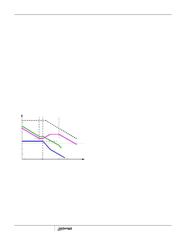
�Figure� 15� shows� an� asymptotic� plot� of� the� DC/DC� converter’s�
�gain� vs.� frequency.� The� actual� Modulator� Gain� has� a� high� gain�
�peak� dependent� on� the� quality� factor� (Q)� of� the� output� filter,�
�which� is� not� shown.� Using� the� previously� mentioned� guidelines�
�should� yield� a� compensation� gain� similar� to� the� curve� plotted.�
�combination� of� the� sense� resistor� and� the� output� resistance�
�of� the� BJT.�
�1�
�(EQ.� 23)�
�where:�
�R� OUT� =� ------------------------------------------------�
�------------------------------------� +� -----�
�r� o�
�The� open� loop� error� amplifier� gain� bounds� the� compensation�
�gain.� Check� the� compensation� gain� at� F� P2� against� the�
�capabilities� of� the� error� amplifier.� The� closed� loop� gain,� G� CL� ,� is�
�constructed� on� the� log-log� graph� of� Figure� 15� by� adding� the�
�1�
�1� 1�
�R301� +� R302�
�(EQ.� 24)�
�modulator� gain,� G� MOD� (in� dB),� to� the� feedback� compensation�
�gain,� G� FB� (in� dB).� This� is� equivalent� to� multiplying� the�
�modulator� transfer� function� and� the� compensation� transfer�
�function� and� then� plotting� the� resulting� gain.�
�For� most� pass� elements,� r� o� is� approximately� 100k� Ω� .�
�It� also� has� a� zero� determined� by� the� ESR� value� of� the� output�
�capacitor� and� the� Capacitance� value� of� the� output� capacitor:�
�F� Z1� =� ---------------------------------------------------�
�F� Z1� F� Z2�
�F� P1�
�F� P2�
�MODULATOR� GAIN�
�COMPENSATION� GAIN�
�1�
�2� π� ?� R� ESR� ?� C� OUT�
�(EQ.� 25)�
�CLOSED� LOOP� GAIN�
�OPEN� LOOP� E/A� GAIN�
�The� compensation� network� is� composed� of� R300,� C300,� the�
�internal� circuitry� of� the� ISL6442,� β� (also� know� as� h� FE� in� data�
�sheets)� of� the� pass� element,� and� the� Miller� capacitance� of�
�the� pass� element.� The� pole� is� located� at:�
�20� log� ?� --------� ?�
�OSC�
�F� P2� =� ----------------------------------�
�0�
�R2�
�?� R1� ?�
�d� MAX� ?� V� IN�
�20� log� ---------------------------------�
�V�
�G� FB�
�where:�
�1�
�2� π� ?� R� X� ?� C� X�
�(EQ.� 26)�
�R� X� =� ------------------------------------------------------------------------�
�--------------� +� --------------------� +� ------------------------�
�G� CL�
�G� MOD�
�1� 1� 1�
�1�
�R300� 1.20k� Ω� 320� Ω� ?� β�
�(EQ.� 27)�
�LOG�
�F� LC�
�F� CE�
�F� 0�
�FREQUENCY�
�and:�
�F� Z2� =� -----------------------------------------------------------�
�FIGURE� 15.� ASYMPTOTIC� BODE� PLOT� OF� CONVERTER� GAIN�
�A� stable� control� loop� has� a� gain� crossing� with� close� to� a�
�-20dB/decade� slope� and� a� phase� margin� greater� than� 45°.�
�Include� worst� case� component� variations� when� determining�
�phase� margin.� The� mathematical� model� presented� makes� a�
�number� of� approximations� and� is� generally� not� accurate� at�
�frequencies� approaching� or� exceeding� half� the� switching�
�frequency.� When� designing� compensation� networks,� select�
�target� crossover� frequencies� in� the� range� of� 10%� to� 30%� of�
�the� switching� frequency,� F� SW� .�
�14�
�C� X� =� C300� +� 180pF� +� C� Miller�
�If� C� Miller� is� unspecified,� use� 1000pF.�
�The� Zero� is� located� at:�
�1�
�2� π� ?� ESR� C300� ?� C300�
�(EQ.� 28)�
�(EQ.� 29)�
�FN9204.2�
�October� 31,� 2008�
�相关PDF资料 |
PDF描述 |
|---|---|
| ISL6445EVAL3Z | EVALUATION BOARD FOR ISL6445 |
| ISL6524EVAL1 | EVALUATION BOARD VRM8.5 ISL6524 |
| ISL6527EVAL1 | EVALUATION BOARD SOIC ISL6527 |
| ISL6532AEVAL1 | EVALUATION BOARD 1 ISL6532A |
| ISL6553EVAL1 | EVALUATION BOARD ISL6553 |
相关代理商/技术参数 |
参数描述 |
|---|---|
| ISL6442IA | 功能描述:IC REG TRPL BCK/LINEAR 24QSOP RoHS:否 类别:集成电路 (IC) >> PMIC - 稳压器 - 线性 + 切换式 系列:- 标准包装:2,500 系列:- 拓扑:降压(降压)同步(3),线性(LDO)(2) 功能:任何功能 输出数:5 频率 - 开关:300kHz 电压/电流 - 输出 1:控制器 电压/电流 - 输出 2:控制器 电压/电流 - 输出 3:控制器 带 LED 驱动器:无 带监控器:无 带序列发生器:是 电源电压:5.6 V ~ 24 V 工作温度:-40°C ~ 85°C 安装类型:* 封装/外壳:* 供应商设备封装:* 包装:* |
| ISL6442IA-TK | 功能描述:IC REG TRPL BCK/LINEAR 24QSOP RoHS:否 类别:集成电路 (IC) >> PMIC - 稳压器 - 线性 + 切换式 系列:- 标准包装:2,500 系列:- 拓扑:降压(降压)同步(3),线性(LDO)(2) 功能:任何功能 输出数:5 频率 - 开关:300kHz 电压/电流 - 输出 1:控制器 电压/电流 - 输出 2:控制器 电压/电流 - 输出 3:控制器 带 LED 驱动器:无 带监控器:无 带序列发生器:是 电源电压:5.6 V ~ 24 V 工作温度:-40°C ~ 85°C 安装类型:* 封装/外壳:* 供应商设备封装:* 包装:* |
| ISL6442IAZ | 功能描述:IC REG TRPL BCK/LINEAR 24QSOP RoHS:是 类别:集成电路 (IC) >> PMIC - 稳压器 - 线性 + 切换式 系列:- 标准包装:2,500 系列:- 拓扑:降压(降压)同步(3),线性(LDO)(2) 功能:任何功能 输出数:5 频率 - 开关:300kHz 电压/电流 - 输出 1:控制器 电压/电流 - 输出 2:控制器 电压/电流 - 输出 3:控制器 带 LED 驱动器:无 带监控器:无 带序列发生器:是 电源电压:5.6 V ~ 24 V 工作温度:-40°C ~ 85°C 安装类型:* 封装/外壳:* 供应商设备封装:* 包装:* |
| ISL6442IAZ-TK | 功能描述:IC REG TRPL BCK/LINEAR 24QSOP RoHS:是 类别:集成电路 (IC) >> PMIC - 稳压器 - 线性 + 切换式 系列:- 标准包装:2,500 系列:- 拓扑:降压(降压)同步(3),线性(LDO)(2) 功能:任何功能 输出数:5 频率 - 开关:300kHz 电压/电流 - 输出 1:控制器 电压/电流 - 输出 2:控制器 电压/电流 - 输出 3:控制器 带 LED 驱动器:无 带监控器:无 带序列发生器:是 电源电压:5.6 V ~ 24 V 工作温度:-40°C ~ 85°C 安装类型:* 封装/外壳:* 供应商设备封装:* 包装:* |
| ISL6442IAZ-TKS2715 | 制造商:Intersil Corporation 功能描述:BROADCOM, ISL6442IAZ-TK BUSINESS TRACKING REQUIREMENTS, SOLD - Tape and Reel |
发布紧急采购,3分钟左右您将得到回复。