参数资料
| 型号: | ISL6539IA-T |
| 厂商: | Intersil |
| 文件页数: | 15/20页 |
| 文件大小: | 0K |
| 描述: | IC CTRLR DDR DRAM, SDRAM 28QSOP |
| 标准包装: | 2,500 |
| 应用: | 控制器,DDR DRAM,SDRAM |
| 输入电压: | 3.3 V ~ 18 V |
| 输出数: | 2 |
| 输出电压: | 0.9 V ~ 5.5 V |
| 工作温度: | -40°C ~ 85°C |
| 安装类型: | 表面贴装 |
| 封装/外壳: | 28-SSOP(0.154",3.90mm 宽) |
| 供应商设备封装: | 28-SSOP/QSOP |
| 包装: | 带卷 (TR) |
�� �
�
�ISL6539�
�Sometimes,� if� the� phase� node� is� very� noisy,� a� resistor� can� be�
�put� on� the� ISEN� pin� to� ground.� This� resistor� together� with� the�
�R� CS� can� divide� the� phase� node� voltage� down,� seen� by� the�
�internal� current� sense� amplifier,� and� reduce� noise� coupling.�
�Sizing� the� Overcurrent� Setpoint� Resistor�
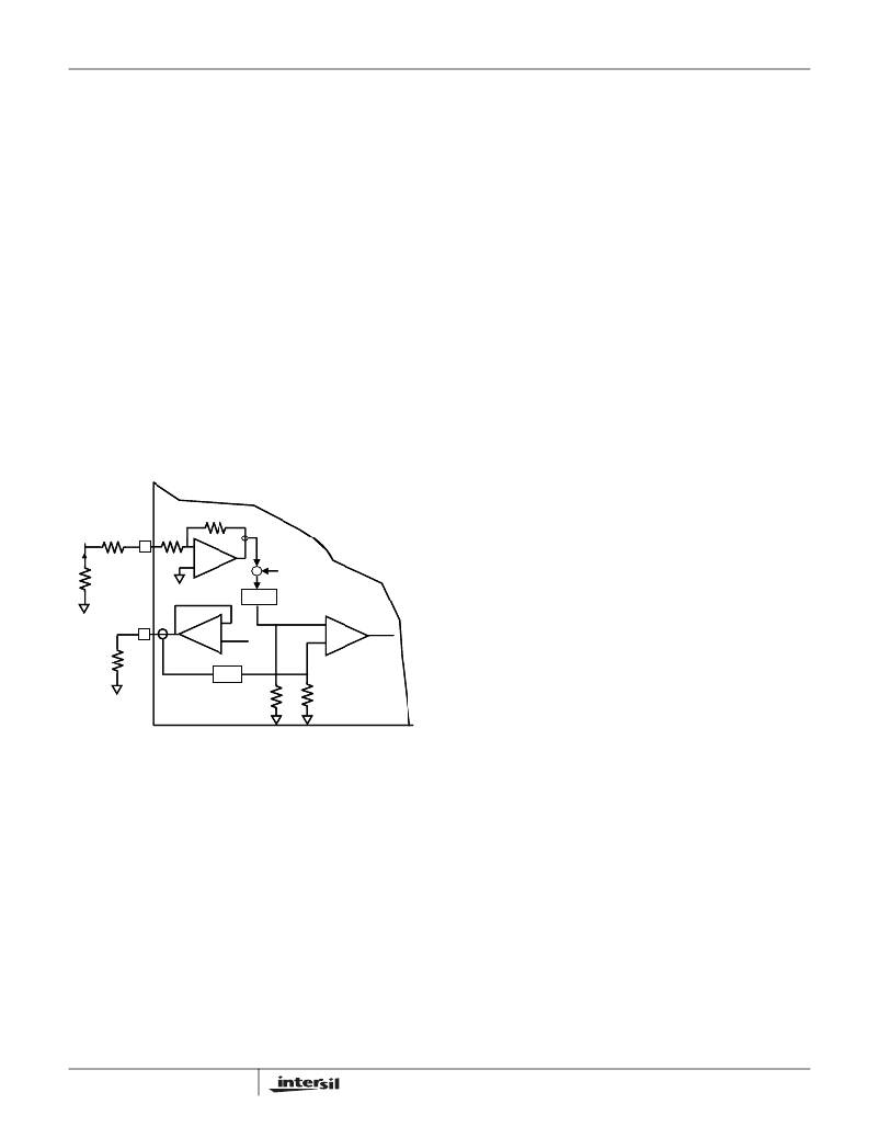
�The� internal� 0.9V� reference� is� buffered� to� the� OCSET� pin�
�with� a� voltage� follower� (refer� to� the� equivalent� circuit� in�
�Figure� 12).� The� current� going� through� the� external�
�overcurrent� set� resistor� is� sensed� from� the� OCSET� pin.� This�
�current,� divided� by� 2.9,� sets� up� the� overcurrent� threshold� and�
�compares� with� the� scaled� ISEN� pin� current� going� through�
�R� CS� with� an� 8μA� offset.� Once� the� sensed� current� is� higher�
�than� the� threshold� value,� an� OC� signal� is� generated.� The� first�
�OC� signal� starts� a� counter� and� activates� a� pulse� skipping�
�function.� The� inductor� current� will� be� continuously� monitored�
�through� the� phase� node� voltage� after� the� first� OC� trip.� As�
�long� as� the� sensed� current� exceeds� the� OC� threshold� value,�
�the� following� PWM� pulse� will� be� skipped.� This� operation� will�
�be� the� same� for� 8� switching� cycles.� Another� OC� occurring�
�between� 8� to� 16� switching� cycles� would� result� in� a� latch� off�
�The� MOSFET� will� not� heat-up� when� applying� a� very� low�
�frequency� and� short� load� pulses� with� an� electronic� load� to�
�the� output.�
�As� an� example,� assume� the� following:�
�?� The� maximum� normal� operation� load� current� is� 1�
�?� The� OC� set� point� is� 10%� higher� than� the� maximum� load�
�current�
�?� The� inductor� peak� current� is� 1.15� to� 1.3� times� higher� than�
�the� load� current,� depending� on� the� inductor� value� and� the�
�input� voltage�
�?� The� r� DS(ON)� has� a� 45%� increase� at� higher� temperature�
�I� OC� should� set� at� least� 1.8� to� 2� times� higher� than� the�
�maximum� load� current� to� avoid� nuisance� overcurrent� trip.�
�Selection� of� the� LC� Filter�
�The� duty� cycle� of� a� buck� converter� is� a� function� of� the� input�
�voltage� and� output� voltage.� Once� an� output� voltage� is� fixed,�
�it� can� be� written� as� Equation� 18:�
�D� (� V� IN� )� =� ----------------�
�with� both� upper� and� lower� drives� low.� If� there� is� no� OC� within�
�8� to� 16� switching� cycles,� normal� operation� resumes.�
�V� OUT�
�V� IN�
�(EQ.� 18)�
�The� switching� frequency,� f� sw� ,� of� ISL6539� is� 300kHz.� The�
�peak-to-peak� ripple� current� going� through� the� inductor� can�
�PHASE� R� CS�
�ISEN�
�140� Ω�
�_�
�be� written� as� Equation� 19:�
�+� Σ� +� 8uA�
�f� sw� ?� L�
�_�
�+�
�DS(ON)�
�r� Rdson�
�+�
�÷� 33.1�
�8μA�
�V� OUT� (� 1� –� D� (� V� IN� )� )�
�I� P� –� P� =� --------------------------------------------------�
�(EQ.� 19)�
�Rset�
�OCSET�
�Amplifier�
�AMPLIFIER�
�_�
�+�
�0.9� V�
�Reference�
�REFERENC� E�
�÷� 2.9�
�SENSE�
�I� Isense�
�+� OC�
�_�
�Comparator�
�COMPARATOR�
�As� higher� ripple� current� will� result� in� higher� switching� loss�
�and� higher� output� voltage� ripple,� the� peak-to-peak� current� of�
�the� inductor� is� generally� designed� with� a� 20%� to� 40%�
�peak-to-peak� ripple� of� the� nominal� operation� current.� Based�
�on� this� assumption,� the� inductor� value� can� be� selected� with�
�Equation� 19.� In� addition� to� the� mechanical� dimension,� a�
�shielded� ferrite� core� inductor� with� a� very� low� DC� resistance,�
�DCR,� is� preferred� for� less� core� loss� and� copper� loss.� The� DC�
�FIGURE� 12.� EQUIVALENT� CIRCUIT� FOR� OC� SIGNAL�
�GENERATOR�
�copper� loss� of� the� inductor� can� be� estimated� by� Equation� 20:�
�P� copper� =� I� load� DCR�
��2�
�(EQ.� 20)�
�R� set� =� ---------------------------------------------------�
�I� OC� r� DS� (� ON� )� (EQ.� 17)�
��10.3V�
�---------------------------------� +� 8� μ� A�
�R� CS� +� 140�
�I� OC� is� the� inductor� peak� current� and� not� the� load� current.�
�Since� inductor� peak� current� changes� with� input� voltage,� it� is�
�better� to� use� an� oscilloscope� when� testing� the� overcurrent�
�setting� point� to� monitor� the� inductor� current,� and� to�
�determine� when� the� OC� occurs.� To� get� consistent� test� results�
�on� different� boards,� it� is� best� to� keep� the� MOSFET� at� a� fixed�
�temperature.�
�15�
�The� inductor� copper� loss� can� be� significant� in� the� total�
�system� power� loss.� Attention� has� to� be� given� to� the� DCR�
�selection.� Another� factor� to� consider� when� choosing� the�
�inductor� is� its� saturation� characteristics� at� elevated�
�temperature.� Saturated� inductors� could� result� in� nuisance�
�OC,� or� OV� trip.�
�Output� voltage� ripple� and� the� transient� voltage� deviation� are�
�factors� that� have� to� be� taken� into� consideration� when�
�selecting� an� output� capacitor.� In� addition� to� high� frequency�
�noise� related� MOSFET� turn-on� and� turn-off,� the� output� voltage�
�ripple� includes� the� capacitance� voltage� drop� and� ESR� voltage�
�FN9144.6�
�April� 29,� 2010�
�相关PDF资料 |
PDF描述 |
|---|---|
| ISL6540AIRZA-T | IC REG CTRLR BUCK PWM VM 28-QFN |
| ISL65426HRZ | IC REG BUCK SYNC ADJ 6A DL 50QFN |
| ISL6545IBZ-T | IC REG CTRLR BUCK PWM VM 8-SOIC |
| ISL6548ACRZA-T | IC REG/CTLR ACPI DUAL DDR 28QFN |
| ISL6548CRZA | IC REG/CTRLR ACPI DUAL DDR 28QFN |
相关代理商/技术参数 |
参数描述 |
|---|---|
| ISL6539IAZ | 功能描述:电流型 PWM 控制器 ISL6539 DL SWITCHER 15V INDUSTRIAL GRD RoHS:否 制造商:Texas Instruments 开关频率:27 KHz 上升时间: 下降时间: 工作电源电压:6 V to 15 V 工作电源电流:1.5 mA 输出端数量:1 最大工作温度:+ 105 C 安装风格:SMD/SMT 封装 / 箱体:TSSOP-14 |
| ISL6539IAZ-T | 功能描述:电流型 PWM 控制器 ISL6539 DL SWITCHER 15V INDUSTRIAL GRD RoHS:否 制造商:Texas Instruments 开关频率:27 KHz 上升时间: 下降时间: 工作电源电压:6 V to 15 V 工作电源电流:1.5 mA 输出端数量:1 最大工作温度:+ 105 C 安装风格:SMD/SMT 封装 / 箱体:TSSOP-14 |
| ISL6540ACRZ | 功能描述:IC REG CTRLR BUCK PWM VM 28-QFN RoHS:是 类别:集成电路 (IC) >> PMIC - 稳压器 - DC DC 切换控制器 系列:- 标准包装:75 系列:- PWM 型:电流模式 输出数:1 频率 - 最大:1MHz 占空比:81% 电源电压:4.3 V ~ 13.5 V 降压:是 升压:是 回扫:是 反相:无 倍增器:无 除法器:无 Cuk:无 隔离:无 工作温度:0°C ~ 70°C 封装/外壳:8-SOIC(0.154",3.90mm 宽) 包装:管件 产品目录页面:1051 (CN2011-ZH PDF) 其它名称:296-2543-5 |
| ISL6540ACRZ-T | 功能描述:IC REG CTRLR BUCK PWM VM 28-QFN RoHS:是 类别:集成电路 (IC) >> PMIC - 稳压器 - DC DC 切换控制器 系列:- 特色产品:LM3753/54 Scalable 2-Phase Synchronous Buck Controllers 标准包装:1 系列:PowerWise® PWM 型:电压模式 输出数:1 频率 - 最大:1MHz 占空比:81% 电源电压:4.5 V ~ 18 V 降压:是 升压:无 回扫:无 反相:无 倍增器:无 除法器:无 Cuk:无 隔离:无 工作温度:-5°C ~ 125°C 封装/外壳:32-WFQFN 裸露焊盘 包装:Digi-Reel® 产品目录页面:1303 (CN2011-ZH PDF) 其它名称:LM3754SQDKR |
| ISL6540ACRZ-TR5453 | 制造商:Intersil Corporation 功能描述:STD. ISL6540ACRZ-T W/GOLD BOND WIRE ONLY - Tape and Reel |
发布紧急采购,3分钟左右您将得到回复。