参数资料
| 型号: | ISL6559CBZ-T |
| 厂商: | Intersil |
| 文件页数: | 11/21页 |
| 文件大小: | 0K |
| 描述: | IC REG CTRLR BUCK PWM VM 28-SOIC |
| 标准包装: | 1 |
| PWM 型: | 电压模式 |
| 输出数: | 1 |
| 频率 - 最大: | 4MHz |
| 占空比: | 75% |
| 电源电压: | 4.75 V ~ 5.25 V |
| 降压: | 是 |
| 升压: | 无 |
| 回扫: | 无 |
| 反相: | 无 |
| 倍增器: | 无 |
| 除法器: | 无 |
| Cuk: | 无 |
| 隔离: | 无 |
| 工作温度: | 0°C ~ 70°C |
| 封装/外壳: | 28-SOIC(0.295",7.50mm 宽) |
| 包装: | 标准包装 |
| 产品目录页面: | 1243 (CN2011-ZH PDF) |
| 其它名称: | ISL6559CBZ-TDKR |
�� �
�
�ISL6559�
�Operation� Initialization�
�Before� converter� operation� is� initialized,� proper� conditions�
�must� exist� on� the� enable� and� disable� inputs.� Once� these�
�conditions� are� met,� the� controller� begins� a� soft-start� interval.�
�Once� the� output� voltage� is� within� the� proper� window� of�
�operation,� the� PGOOD� output� changes� state� to� update� an�
�external� system� monitor.�
�Enable� and� Disable�
�The� PWM� outputs� are� held� in� a� high-impedance� state� to�
�assure� the� drivers� remain� off� while� in� shutdown� mode.� Four�
�separate� input� conditions� must� be� met� before� the� ISL6559� is�
�released� from� shutdown� mode.�
�First,� the� bias� voltage� applied� at� VCC� must� reach� the� internal�
�power-on� reset� (POR)� circuit� rising� threshold.� Once� this�
�threshold� is� met,� the� EN� input� signal� becomes� the� gate� for�
�The� 11111� VID� code� is� reserved� as� a� signal� to� the� controller�
�that� no� load� is� present.� The� controller� will� enter� shutdown�
�mode� after� receiving� this� code� and� will� start� up� upon�
�receiving� any� other� code.� This� code� is� not� intended� as� a�
�means� of� enabling� the� controller� when� a� load� is� present.�
�To� enable� the� controller,� VCC� must� be� greater� than� the� POR�
�threshold;� the� voltage� on� EN� must� be� greater� than� 1.23V;�
�FS/DIS� must� not� be� grounded;� and� VID� cannot� be� equal� to�
�11111.� Once� these� conditions� are� true,� the� controller�
�immediately� initiates� a� soft-start� sequence.�
�Soft-Start�
�The� soft-start� time,� t� SS� ,� is� determined� by� an� 11-bit� counter�
�that� increments� with� every� pulse� of� the� phase� clock.� For�
�example,� a� converter� switching� at� 250kHz� per� phase� has� a�
�soft-start� time� of�
�T� SS� =� -------------� =� 8.3ms�
�soft-start� initialization.� Hysteresis� between� the� rising� and�
�falling� thresholds� insures� that� once� enabled,� the� ISL6559� will�
�2048�
�f� SW�
�(EQ.� 9)�
�not� inadvertently� turn� off� unless� the� bias� voltage� drops�
�substantially.� See� Electrical� Specifications� for� specifics� on�
�POR� rising� and� falling� thresholds.�
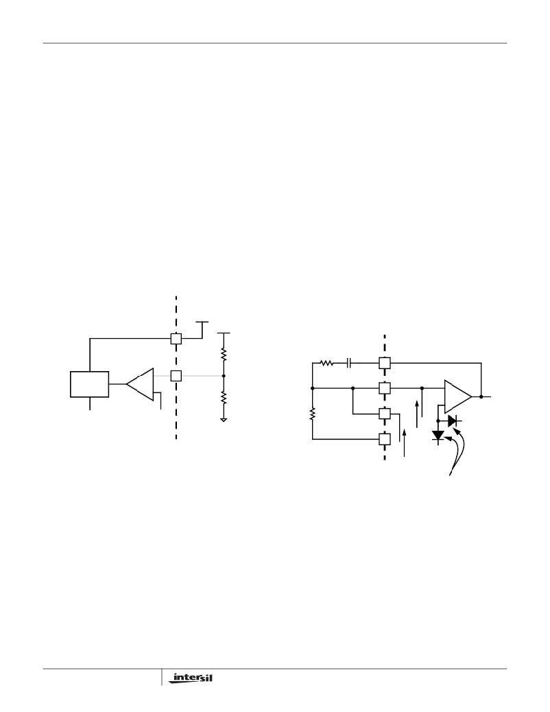
�ISL6559� INTERNAL� CIRCUIT� EXTERNAL� CIRCUIT�
�+� 5V�
�During� the� soft-start� interval,� the� soft-start� voltage,� V� RAM� P� ,�
�increases� linearly� from� zero� to� 140%� of� the� programmed�
�DAC� voltage.� At� the� same� time� a� current� source,� I� RAMP� ,� is�
�decreasing� from� 160� μ� A� down� to� zero.� These� signals� are�
�connected� as� shown� in� Figure� 8� (I� OUT� may� or� may� not� be�
�connected� to� FB� depending� on� the� particular� application).�
�VCC�
�+� 12� V�
�EXTERNAL� CIRCUIT�
�ISL6559� INTERNAL� CIRCUIT�
�ENABLE�
�COMPARATOR�
�10.7k� ?�
�R� C�
�C� C�
�COMP�
�POR�
�CIRCUIT�
�OV� LATCH�
�SIGNAL�
�+�
�-�
�1.23V� (±� 2%)�
�EN�
�1.40k� ?�
�R� FB�
�FB�
�IOUT�
�ERROR� AMPLIFIER�
�-�
�+� V� COMP�
�REFERENCE�
�VOLTAGE�
�FIGURE� 7.� POWER� SEQUENCING� USING� THRESHOLD-�
�SENSITIVE� ENABLE� (EN)� FUNCTION�
�Second,� the� ISL6559� features� an� enable� input� (EN)� for�
�VDIFF�
�I� AVG�
�I� RAMP�
�V� RAMP�
�IDEAL� DIODES�
�power� sequencing� between� the� controller� bias� voltage� and�
�another� voltage� rail.� The� enable� comparator� holds� the�
�ISL6559� in� shutdown� until� the� voltage� at� EN� rises� above�
�1.23V.� The� enable� comparator� has� about� 90mV� of� hysteresis�
�to� prevent� bounce.� It� is� important� that� the� driver� ICs� reach�
�their� POR� level� before� the� ISL6559� becomes� enabled.� The�
�schematic� in� Figure� 7� demonstrates� sequencing� the� ISL6559�
�with� the� HIP660X� family� of� Intersil� MOSFET� drivers� which�
�require� 12V� bias.�
�Third,� the� frequency� select\disable� input� (FS/DIS)� will�
�shutdown� the� converter� when� pulled� to� ground.� Under� this�
�condition,� the� internal� oscillator� is� disabled.� The� oscillator�
�resumes� operation� upon� release� of� FS/DIS� and� a� soft-start�
�sequence� is� initiated.�
�11�
�FIGURE� 8.� RAMP� CURRENT� AND� VOLTAGE� FOR�
�REGULATING� SOFT-START� SLOPE�
�AND� DURATION�
�The� ideal� diodes� in� Figure� 8� assure� that� the� controller� tries� to�
�regulate� its� output� to� the� lower� of� either� the� reference� voltage�
�or� V� RAM� P� .� Since� I� RAMP� creates� an� initial� offset� across� R� FB� of�
�(R� FB� x� 160� μ� A),� the� first� PWM� pulse� will� not� be� seen� until�
�V� RAMP� is� greater� than� the� R� F� B� I� RAMP� offset.� This� produces� a�
�delay� after� the� ISL6559� enables� before� the� output� voltage�
�starts� moving.� For� example,� if� VID� =� 1.5V,� R� FB� =� 1k� ?� and� T� SS�
�=� 8.3ms,� the� delay� time� can� be� expressed� using� Equation� 10.�
�FN9084.8�
�December� 29,� 2004�
�相关PDF资料 |
PDF描述 |
|---|---|
| ISL6561CR-T | IC CTRLR PWM MULTIPHASE 40-QFN |
| ISL6563IR-T | IC CTRLR PWM MULTIPHASE 24-QFN |
| ISL6564AIRZ | IC REG CTRLR BUCK PWM VM 40-QFN |
| ISL6564IR-T | IC REG CTRLR BUCK PWM VM 40-QFN |
| ISL6565BCV-T | IC REG CTRLR BUCK PWM VM 28TSSOP |
相关代理商/技术参数 |
参数描述 |
|---|---|
| ISL6559CR | 功能描述:IC REG CTRLR BUCK PWM VM 32-QFN RoHS:否 类别:集成电路 (IC) >> PMIC - 稳压器 - DC DC 切换控制器 系列:- 标准包装:4,000 系列:- PWM 型:电压模式 输出数:1 频率 - 最大:1.5MHz 占空比:66.7% 电源电压:4.75 V ~ 5.25 V 降压:是 升压:无 回扫:无 反相:无 倍增器:无 除法器:无 Cuk:无 隔离:无 工作温度:-40°C ~ 85°C 封装/外壳:40-VFQFN 裸露焊盘 包装:带卷 (TR) |
| ISL6559CR-T | 功能描述:IC REG CTRLR BUCK PWM VM 32-QFN RoHS:否 类别:集成电路 (IC) >> PMIC - 稳压器 - DC DC 切换控制器 系列:- 标准包装:4,000 系列:- PWM 型:电压模式 输出数:1 频率 - 最大:1.5MHz 占空比:66.7% 电源电压:4.75 V ~ 5.25 V 降压:是 升压:无 回扫:无 反相:无 倍增器:无 除法器:无 Cuk:无 隔离:无 工作温度:-40°C ~ 85°C 封装/外壳:40-VFQFN 裸露焊盘 包装:带卷 (TR) |
| ISL6559CRZ | 功能描述:电流型 PWM 控制器 2 TO 4 PHS BUCK CNTRLR 32L 5X5 MLFP RoHS:否 制造商:Texas Instruments 开关频率:27 KHz 上升时间: 下降时间: 工作电源电压:6 V to 15 V 工作电源电流:1.5 mA 输出端数量:1 最大工作温度:+ 105 C 安装风格:SMD/SMT 封装 / 箱体:TSSOP-14 |
| ISL6559CRZR5265 | 功能描述:IC REG CTRLR BUCK PWM VM 32-QFN RoHS:是 类别:集成电路 (IC) >> PMIC - 稳压器 - DC DC 切换控制器 系列:- 产品培训模块:Lead (SnPb) Finish for COTS Obsolescence Mitigation Program 标准包装:2,500 系列:- PWM 型:电流模式 输出数:1 频率 - 最大:275kHz 占空比:50% 电源电压:18 V ~ 110 V 降压:无 升压:无 回扫:无 反相:无 倍增器:无 除法器:无 Cuk:无 隔离:是 工作温度:-40°C ~ 85°C 封装/外壳:8-SOIC(0.154",3.90mm 宽) 包装:带卷 (TR) |
| ISL6559CRZ-T | 功能描述:电流型 PWM 控制器 2 TO 4 PHS BUCK CNTRLR 32L 5X5 MLFP RoHS:否 制造商:Texas Instruments 开关频率:27 KHz 上升时间: 下降时间: 工作电源电压:6 V to 15 V 工作电源电流:1.5 mA 输出端数量:1 最大工作温度:+ 105 C 安装风格:SMD/SMT 封装 / 箱体:TSSOP-14 |
发布紧急采购,3分钟左右您将得到回复。