参数资料
| 型号: | ISL6563IR-T |
| 厂商: | Intersil |
| 文件页数: | 18/19页 |
| 文件大小: | 0K |
| 描述: | IC CTRLR PWM MULTIPHASE 24-QFN |
| 标准包装: | 6,000 |
| 应用: | 控制器,Intel VRM9,VRM10,AMD Hammer 应用 |
| 输入电压: | 5 V ~ 12 V |
| 输出数: | 1 |
| 输出电压: | 0.8 V ~ 1.85 V |
| 工作温度: | -40°C ~ 85°C |
| 安装类型: | 表面贴装 |
| 封装/外壳: | 24-VFQFN 裸露焊盘 |
| 供应商设备封装: | 24-QFN(4x4) |
| 包装: | 带卷 (TR) |
�� �
�
�ISL6563�
�I� L� ,� PP� =� --------------------------------� � ----------------�
�The� output� inductor� of� each� power� channel� controls� the� ripple�
�current.� The� control� IC� is� stable� for� channel� ripple� current�
�(peak-to-peak)� up� to� twice� the� average� current.� A� single�
�channel’s� ripple� current� is� approximated� using� Equation� 25:�
�V� IN� –� V� OUT� V� OUT� (EQ.� 25)�
�F� SW� ?� L� V� IN�
�The� current� from� multiple� channels� tend� to� cancel� each� other�
�and� reduce� the� total� ripple� current.� The� total� output� ripple�
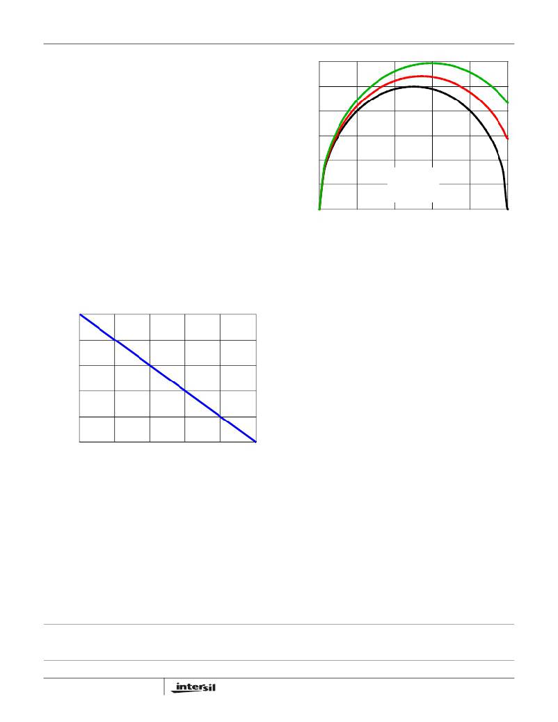
�current� can� be� determined� using� the� curve� in� Figure� 10;� it�
�provides� the� total� ripple� current� as� a� function� of� duty� cycle�
�and� number� of� active� channels,� normalized� to� the� parameter�
�0.3�
�0.2�
�0.1�
�I� L,PP� =� 0�
�L� ?� F� SW�
�K� NORM� at� zero� duty� cycle.�
�V� OUT�
�K� NORM� =� --------------------�
�(EQ.� 26)�
�0�
�0�
�0.1�
�I� L,PP� =� 0.5� x� I� O�
�I� L,PP� =� 0.75� x� I� O�
�0.2� 0.3�
�0.4�
�0.5�
�Δ� I� TOTAL� =� K� NORM� ?� K� CM�
�where� L� is� the� channel� inductor� value.�
�Find� the� intersection� of� the� active� channel� curve� and� duty�
�cycle� for� your� particular� application.� The� resulting� ripple�
�current� multiplier� from� the� y-axis� is� then� multiplied� by� the�
�normalization� factor,� K� NORM� ,� to� determine� the� total� output�
�ripple� current� for� the� given� application.�
�(EQ.� 27)�
�1.0�
�0.8�
�0.6�
�0.4�
�0.2�
�DUTY� CYCLE� (V� O� /V� IN� )�
�FIGURE� 11.� NORMALIZED� INPUT� RMS� CURRENT� vs� DUTY�
�CYCLE� FOR� A� 2-PHASE� CONVERTER�
�As� the� input� capacitors� are� responsible� for� sourcing� the� AC�
�component� of� the� input� current� flowing� into� the� upper�
�MOSFETs,� their� RMS� current� capacity� must� be� sufficient� to�
�handle� the� AC� component� of� the� current� drawn� by� the� upper�
�MOSFETs.� Figure� 11� can� be� used� to� determine� the� input�
�capacitor� RMS� current� function� of� duty� cycle,� maximum�
�sustained� output� current� (I� O� ),� and� the� ratio� of� the� peak-to-peak�
�inductor� current� (I� L,PP� )� to� the� maximum� sustained� load� current,�
�I� O� .� Figure� 11� can� also� be� used� as� a� reference� demonstrating�
�the� dramatic� reduction� in� input� capacitor� RMS� current� in� a� 2-�
�phase� DC/DC� converter,� as� compared� to� a� single-phase�
�regulator.�
�Use� a� mix� of� input� bypass� capacitors� to� control� the� input�
�voltage� ripple.� Use� ceramic� capacitance� for� the� high�
�frequency� decoupling� and� bulk� capacitors� to� supply� the�
�RMS� current.� Minimize� the� connection� path� inductance� of�
�0�
�0� 0.1� 0.2� 0.3� 0.4�
�DUTY� CYCLE� (V� O� /V� IN� )�
�FIGURE� 10.� RIPPLE� CURRENT� vs� DUTY� CYCLE�
�0.5�
�the� high� frequency� decoupling� ceramic� capacitors� (from�
�drain� of� upper� MOSFET� to� source� of� lower� MOSFET).�
�For� bulk� capacitance,� several� electrolytic� or� high-capacity� MLC�
�Input� Capacitor� Selection�
�The� important� parameters� for� the� bulk� input� capacitors� are�
�the� voltage� rating� and� the� RMS� current� rating.� For� reliable�
�operation,� select� bulk� input� capacitors� with� voltage� and�
�current� ratings� above� the� maximum� input� voltage� and�
�capacitors� may� be� needed.� For� surface� mount� designs,� solid�
�tantalum� capacitors� can� be� used,� but� caution� must� be�
�exercised� with� regard� to� the� capacitor� surge� current� rating.�
�These� capacitors� must� be� capable� of� handling� the� surge-�
�current� at� power-up.�
�largest� RMS� current� required� by� the� circuit.� The� capacitor�
�voltage� rating� should� be� at� least� 1.25� times� greater� than� the�
�maximum� input� voltage.� The� input� RMS� current� required� for�
�a� multiphase� converter� can� be� approximated� with� the� aid� of�
�Figure� 11.�
�All� Intersil� U.S.� products� are� manufactured,� assembled� and� tested� utilizing� ISO9000� quality� systems.�
�Intersil� Corporation’s� quality� certifications� can� be� viewed� at� www.intersil.com/design/quality�
�Intersil� products� are� sold� by� description� only.� Intersil� Corporation� reserves� the� right� to� make� changes� in� circuit� design,� software� and/or� specifications� at� any� time� without�
�notice.� Accordingly,� the� reader� is� cautioned� to� verify� that� data� sheets� are� current� before� placing� orders.� Information� furnished� by� Intersil� is� believed� to� be� accurate� and�
�reliable.� However,� no� responsibility� is� assumed� by� Intersil� or� its� subsidiaries� for� its� use;� nor� for� any� infringements� of� patents� or� other� rights� of� third� parties� which� may� result�
�from� its� use.� No� license� is� granted� by� implication� or� otherwise� under� any� patent� or� patent� rights� of� Intersil� or� its� subsidiaries.�
�For� information� regarding� Intersil� Corporation� and� its� products,� see� www.intersil.com�
�18�
�FN9126.8�
�June� 10,� 2010�
�相关PDF资料 |
PDF描述 |
|---|---|
| ISL6564AIRZ | IC REG CTRLR BUCK PWM VM 40-QFN |
| ISL6564IR-T | IC REG CTRLR BUCK PWM VM 40-QFN |
| ISL6565BCV-T | IC REG CTRLR BUCK PWM VM 28TSSOP |
| ISL6566AIRZ | IC CTRLR PWM 3PHASE BUCK 40-QFN |
| ISL6566CRZ-T | IC CTLR PWM BUCK 3PHASE 40-QFN |
相关代理商/技术参数 |
参数描述 |
|---|---|
| ISL6563IRZ | 功能描述:电流型 PWM 控制器 P6 TWO PHS CONT INTEGRTD DRVRS DESKT RoHS:否 制造商:Texas Instruments 开关频率:27 KHz 上升时间: 下降时间: 工作电源电压:6 V to 15 V 工作电源电流:1.5 mA 输出端数量:1 最大工作温度:+ 105 C 安装风格:SMD/SMT 封装 / 箱体:TSSOP-14 |
| ISL6563IRZ-T | 功能描述:电流型 PWM 控制器 P6 TWO PHS CONT INTEGRTD DRVRS DESKT RoHS:否 制造商:Texas Instruments 开关频率:27 KHz 上升时间: 下降时间: 工作电源电压:6 V to 15 V 工作电源电流:1.5 mA 输出端数量:1 最大工作温度:+ 105 C 安装风格:SMD/SMT 封装 / 箱体:TSSOP-14 |
| ISL6564ACRZ | 功能描述:IC REG CTRLR BUCK PWM VM 40-QFN RoHS:是 类别:集成电路 (IC) >> PMIC - 稳压器 - DC DC 切换控制器 系列:- 产品培训模块:Lead (SnPb) Finish for COTS Obsolescence Mitigation Program 标准包装:2,500 系列:- PWM 型:电流模式 输出数:1 频率 - 最大:275kHz 占空比:50% 电源电压:18 V ~ 110 V 降压:无 升压:无 回扫:无 反相:无 倍增器:无 除法器:无 Cuk:无 隔离:是 工作温度:-40°C ~ 85°C 封装/外壳:8-SOIC(0.154",3.90mm 宽) 包装:带卷 (TR) |
| ISL6564ACRZ-T | 功能描述:IC REG CTRLR BUCK PWM VM 40-QFN RoHS:是 类别:集成电路 (IC) >> PMIC - 稳压器 - DC DC 切换控制器 系列:- 产品培训模块:Lead (SnPb) Finish for COTS Obsolescence Mitigation Program 标准包装:2,500 系列:- PWM 型:电流模式 输出数:1 频率 - 最大:275kHz 占空比:50% 电源电压:18 V ~ 110 V 降压:无 升压:无 回扫:无 反相:无 倍增器:无 除法器:无 Cuk:无 隔离:是 工作温度:-40°C ~ 85°C 封装/外壳:8-SOIC(0.154",3.90mm 宽) 包装:带卷 (TR) |
| ISL6564AIRZ | 功能描述:IC REG CTRLR BUCK PWM VM 40-QFN RoHS:是 类别:集成电路 (IC) >> PMIC - 稳压器 - DC DC 切换控制器 系列:- 产品培训模块:Lead (SnPb) Finish for COTS Obsolescence Mitigation Program 标准包装:2,500 系列:- PWM 型:电流模式 输出数:1 频率 - 最大:275kHz 占空比:50% 电源电压:18 V ~ 110 V 降压:无 升压:无 回扫:无 反相:无 倍增器:无 除法器:无 Cuk:无 隔离:是 工作温度:-40°C ~ 85°C 封装/外壳:8-SOIC(0.154",3.90mm 宽) 包装:带卷 (TR) |
发布紧急采购,3分钟左右您将得到回复。