参数资料
| 型号: | ISL6566CRZ-T |
| 厂商: | Intersil |
| 文件页数: | 17/29页 |
| 文件大小: | 0K |
| 描述: | IC CTLR PWM BUCK 3PHASE 40-QFN |
| 标准包装: | 1 |
| 应用: | 控制器,Intel VRM9,VRM10,AMD Hammer 应用 |
| 输入电压: | 3 V ~ 12 V |
| 输出数: | 1 |
| 输出电压: | 0.8 V ~ 1.6 V |
| 工作温度: | 0°C ~ 70°C |
| 安装类型: | 表面贴装 |
| 封装/外壳: | 40-VFQFN 裸露焊盘 |
| 供应商设备封装: | 40-QFN(6x6) |
| 包装: | 标准包装 |
| 其它名称: | ISL6566CRZ-TDKR |
第1页第2页第3页第4页第5页第6页第7页第8页第9页第10页第11页第12页第13页第14页第15页第16页当前第17页第18页第19页第20页第21页第22页第23页第24页第25页第26页第27页第28页第29页
�� �
�
�ISL6566�
�Advanced� Adaptive� Zero� Shoot-Through� Deadtime�
�Control� (Patent� Pending)�
�The� integrated� drivers� incorporate� a� unique� adaptive� deadtime�
�control� technique� to� minimize� deadtime,� resulting� in� high�
�efficiency� from� the� reduced� freewheeling� time� of� the� lower�
�MOSFET� body-diode� conduction,� and� to� prevent� the� upper� and�
�lower� MOSFETs� from� conducting� simultaneously.� This� is�
�accomplished� by� ensuring� either� rising� gate� turns� on� its�
�1.6�
�1.4�
�1.2�
�1.�
�0.8�
�MOSFET� with� minimum� and� sufficient� delay� after� the� other� has�
�turned� off.�
�0.6�
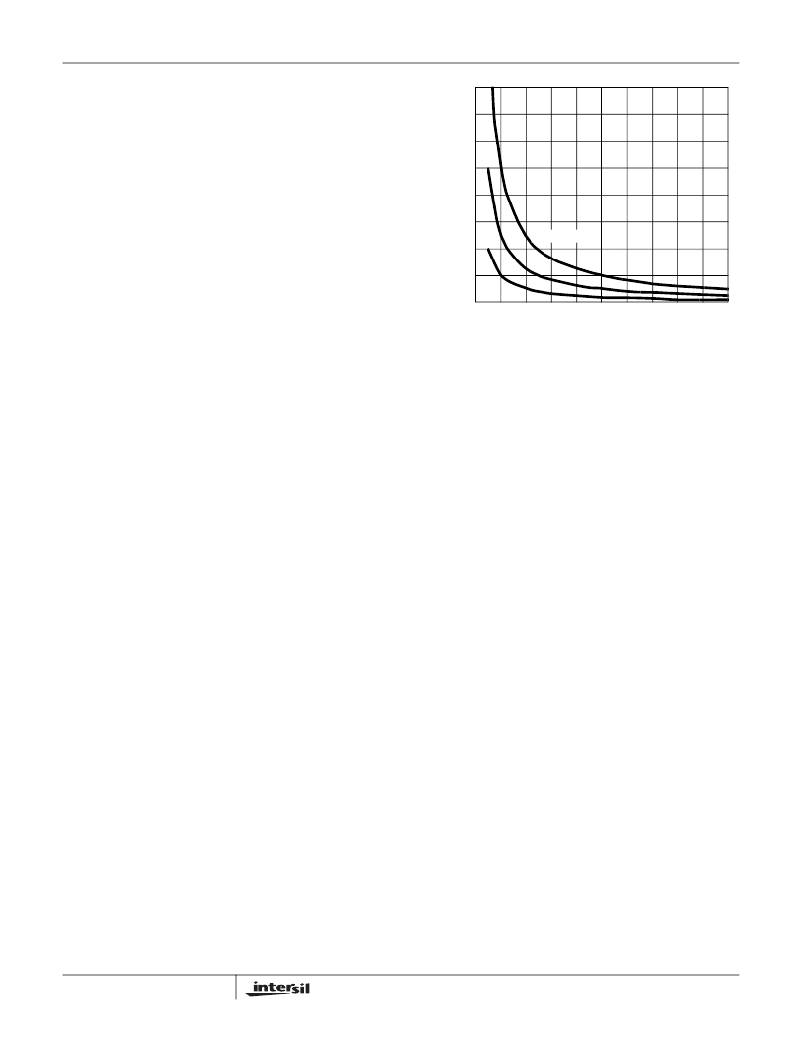
�Q� GATE� = 100nC�
�During� turn-off� of� the� lower� MOSFET,� the� PHASE� voltage� is�
�monitored� until� it� reaches� a� -0.3V/+0.8V� trip� point� for� a�
�forward/reverse� current,� at� which� time� the� UGATE� is� released�
�0.4�
�0.2�
�20nC�
�50nC�
�to� rise.� An� auto-zero� comparator� is� used� to� correct� the� r� DS(ON)�
�drop� in� the� phase� voltage� preventing� false� detection� of� the�
�-0.3V� phase� level� during� r� DS(ON� conduction� period.� In� the� case�
�of� zero� current,� the� UGATE� is� released� after� 35ns� delay� of� the�
�LGATE� dropping� below� 0.5V.� During� the� phase� detection,� the�
�disturbance� of� LGATE� falling� transition� on� the� PHASE� node� is�
�blanked� out� to� prevent� falsely� tripping.� Once� the� PHASE� is�
�high,� the� advanced� adaptive� shoot-through� circuitry� monitors�
�the� PHASE� and� UGATE� voltages� during� a� PWM� falling� edge�
�and� the� subsequent� UGATE� turn-off.� If� either� the� UGATE� falls�
�to� less� than� 1.75V� above� the� PHASE� or� the� PHASE� falls� to� less�
�than� +0.8V,� the� LGATE� is� released� to� turn� on.�
�Internal� Bootstrap� Device�
�All� three� integrated� drivers� feature� an� internal� bootstrap�
�schottky� diode.� Simply� adding� an� external� capacitor� across�
�the� BOOT� and� PHASE� pins� completes� the� bootstrap� circuit.�
�The� bootstrap� function� is� also� designed� to� prevent� the�
�bootstrap� capacitor� from� overcharging� due� to� the� large�
�negative� swing� at� the� PHASE� node.� This� reduces� voltage�
�stress� on� the� boot� to� phase� pins.�
�The� bootstrap� capacitor� must� have� a� maximum� voltage�
�rating� above� PVCC� +� 5V� and� its� capacitance� value� can� be�
�chosen� from� the� following� equation:�
�0.0�
�0.0� 0.1� 0.2� 0.3� 0.4� 0.5� 0.6� 0.7� 0.8� 0.9� 1.0�
�?� V� BOOT_CAP� (V)�
�FIGURE� 10.� BOOTSTRAP� CAPACITANCE� vs� BOOT� RIPPLE�
�VOLTAGE�
�Gate� Drive� Voltage� Versatility�
�The� ISL6566� provides� the� user� flexibility� in� choosing� the�
�gate� drive� voltage� for� efficiency� optimization.� The� controller�
�ties� the� upper� and� lower� drive� rails� together.� Simply� applying�
�a� voltage� from� 5V� up� to� 12V� on� PVCC� sets� both� gate� drive�
�rail� voltages� simultaneously.�
�Initialization�
�Prior� to� initialization,� proper� conditions� must� exist� on� the�
�ENLL,� VCC,� PVCC� and� the� VID� pins.� When� the� conditions� are�
�met,� the� controller� begins� soft-start.� Once� the� output� voltage� is�
�within� the� proper� window� of� operation,� the� controller� asserts�
�PGOOD.�
�Enable� and� Disable�
�While� in� shutdown� mode,� the� PWM� outputs� are� held� in� a�
�high-impedance� state.� This� forces� the� drivers� to� short� gate-�
�to-source� of� the� upper� and� lower� MOSFET’s� to� assure� the�
�MOSFETs� remain� off.� The� following� input� conditions� must� be�
�C� BOOT_CAP� ≥� --------------------------------------�
�Q� GATE�
�?� V� BOOT_CAP�
�(EQ.� 12)�
�met� before� the� ISL6566� is� released� from� this� shutdown�
�mode.�
�Q� GATE� =� ------------------------------------� ?� N� Q1�
�Q� G1� ?� PVCC�
�V� GS1�
�where� Q� G1� is� the� amount� of� gate� charge� per� upper� MOSFET�
�at� V� GS1� gate-source� voltage� and� N� Q1� is� the� number� of�
�control� MOSFETs.� The� ?� V� BOOT_CAP� term� is� defined� as� the�
�allowable� droop� in� the� rail� of� the� upper� gate� drive.�
�17�
�1.� The� bias� voltage� applied� at� VCC� must� reach� the� internal�
�power-on� reset� (POR)� rising� threshold.� Once� this�
�threshold� is� reached,� proper� operation� of� all� aspects� of�
�the� ISL6566� is� guaranteed.� Hysteresis� between� the� rising�
�and� falling� thresholds� assure� that� once� enabled,� the�
�ISL6566� will� not� inadvertently� turn� off� unless� the� bias�
�voltage� drops� substantially� (see� Electrical�
�Specifications� ).�
�FN9178.4�
�March� 9,� 2006�
�相关PDF资料 |
PDF描述 |
|---|---|
| ISL6567CRZ | IC REG CTRLR BUCK PWM VM 24-QFN |
| ISL6568CRZ-T | IC CTLR PWM BUCK 2PHASE 32-QFN |
| ISL6569ACR-T | IC REG CTRLR BUCK PWM 32-QFN |
| ISL6569CR-T | IC REG CTRLR DIVIDER PWM 32-QFN |
| ISL6571CRZ | IC MOSF DRVR/SYNC SW COMPL 68QFN |
相关代理商/技术参数 |
参数描述 |
|---|---|
| ISL6566CRZ-TR5184 | 功能描述:IC CTRLR PWM 3PHASE BUCK 40-QFN RoHS:是 类别:集成电路 (IC) >> PMIC - 稳压器 - 专用型 系列:- 标准包装:2,000 系列:- 应用:控制器,DSP 输入电压:4.5 V ~ 25 V 输出数:2 输出电压:最低可调至 1.2V 工作温度:-40°C ~ 85°C 安装类型:表面贴装 封装/外壳:30-TFSOP(0.173",4.40mm 宽) 供应商设备封装:30-TSSOP 包装:带卷 (TR) |
| ISL6566EVAL1 | 功能描述:EVAL BOARD 1 FOR ISL6566 RoHS:否 类别:编程器,开发系统 >> 评估板 - 线性稳压器 (LDO) 系列:* 产品变化通告:1Q2012 Discontinuation 30/Mar/2012 设计资源:NCP590MNDPTAGEVB Gerber Files 标准包装:1 系列:- 每 IC 通道数:2 - 双 输出电压:1.8V,2.8V 电流 - 输出:300mA 输入电压:2.1 ~ 5.5 V 稳压器类型:正,固定式 工作温度:-40°C ~ 85°C 板类型:完全填充 已供物品:板 已用 IC / 零件:NCP590MNDP 其它名称:NCP590MNDPTAGEVB-NDNCP590MNDPTAGEVBOS |
| ISL6566IR | 功能描述:IC CTRLR PWM BUCK 3PHASE 40-QFN RoHS:否 类别:集成电路 (IC) >> PMIC - 稳压器 - 专用型 系列:- 产品培训模块:Lead (SnPb) Finish for COTS Obsolescence Mitigation Program 标准包装:2,000 系列:- 应用:电源,ICERA E400,E450 输入电压:4.1 V ~ 5.5 V 输出数:10 输出电压:可编程 工作温度:-40°C ~ 85°C 安装类型:表面贴装 封装/外壳:42-WFBGA,WLCSP 供应商设备封装:42-WLP 包装:带卷 (TR) |
| ISL6566IR-T | 功能描述:IC CTRLR PWM BUCK 3PHASE 40-QFN RoHS:否 类别:集成电路 (IC) >> PMIC - 稳压器 - 专用型 系列:- 产品培训模块:Lead (SnPb) Finish for COTS Obsolescence Mitigation Program 标准包装:2,000 系列:- 应用:电源,ICERA E400,E450 输入电压:4.1 V ~ 5.5 V 输出数:10 输出电压:可编程 工作温度:-40°C ~ 85°C 安装类型:表面贴装 封装/外壳:42-WFBGA,WLCSP 供应商设备封装:42-WLP 包装:带卷 (TR) |
| ISL6566IRZ | 功能描述:IC CTRLR PWM BUCK 3PHASE 40-QFN RoHS:是 类别:集成电路 (IC) >> PMIC - 稳压器 - 专用型 系列:- 标准包装:43 系列:- 应用:控制器,Intel VR11 输入电压:5 V ~ 12 V 输出数:1 输出电压:0.5 V ~ 1.6 V 工作温度:-40°C ~ 85°C 安装类型:表面贴装 封装/外壳:48-VFQFN 裸露焊盘 供应商设备封装:48-QFN(7x7) 包装:管件 |
发布紧急采购,3分钟左右您将得到回复。